DFM Before Committing to Production Tooling
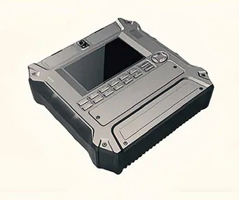
A prototype can confirm the overall shape, internal space, and assembly concept, but it does not prove that the same design can be injection molded consistently. Before mold design began, our engineers reviewed the 3D files and assembly information with the customer.
The injection molding DFM concentrated on the decisions most likely to affect tooling cost, appearance, and production stability:
Wall-thickness transitions and the risk of sink marks on exterior surfaces
Draft angles for clean release without damaging visible areas
Gate locations and their influence on filling, weld lines, and gate vestige
Parting-line placement around the enclosure's cosmetic surfaces
Undercuts and openings that required sliders or other side actions
Bosses, ribs, and locating features that controlled PCB and enclosure assembly
Ejection, venting, and cooling for consistent molding of the larger panels
Because the housings had to fit together, these points were reviewed as one assembly. A change that improved mold release could also alter an enclosure gap or internal mounting position. Questions were resolved with the customer before steel cutting wherever possible, reducing the risk of expensive corrections later.
Mold Design Based on the Actual Production Need
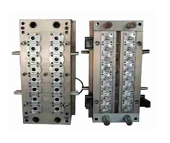
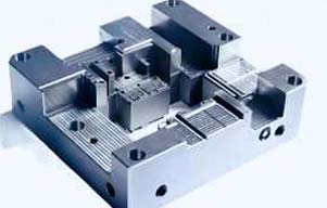
After DFM approval, the tooling plan was developed around the customer's expected product demand and part requirements. The discussion covered mold structure, gate strategy, sliders, cooling, ejection, and suitable mold steel rather than defaulting to an unnecessarily complex tool.
The enclosure's large exterior panels required balanced filling and controlled cooling to limit distortion and visible surface defects. Ventilation slots and interface openings needed stable definition. Internal ribs and screw bosses had to provide assembly support without causing excessive sink on the opposite cosmetic face. Recessed features that could not release in the main opening direction were handled through the agreed side-action design.
This review gave the customer a clear tooling plan before mold manufacturing started and kept the engineering decisions tied to actual production requirements.
First Mold Trial in Approximately One Month
Following approval of the DFM and mold design, the tool components were machined, fitted, and assembled. The first mold trial was completed in approximately one month.
T1 samples were treated as engineering validation parts, not automatic production approval. The review covered filling, flash, weld lines, surface condition, ejection, deformation, and key dimensions. The separate housing sections were also assembled to check interface gaps, opening alignment, internal mounting locations, and whether the enclosure closed without force.
Trial findings were translated into defined actions. Depending on the issue, the response included molding-parameter adjustment, improved venting, local tool correction, shutoff adjustment, or refinement of a fit-related dimension.
Two to Three Trials Before Final Approval
The mold went through two to three trial and sample-review rounds. Each round had a specific purpose: verify the previous correction, confirm dimensions and appearance, and check the complete enclosure again. This avoided approving individual molded parts that might later create problems during final assembly.
Once the molding condition and geometry were stable, samples were painted and screen printed. Reviewing finished parts allowed the customer to confirm color, gloss, graphic position, text alignment, and visual consistency across the mating housings. Coating also made it easier to identify surface imperfections that might be less noticeable on unfinished ABS.
Batch injection molding began only after the molded components, surface finish, printing, and assembled enclosure were approved.
A Clear Approval Path for R&D Teams
For an R&D engineer or product owner, the important result is not simply a completed mold. It is a controlled transfer into production with clear review points:
1. Prototype assembly confirmed
2. DFM issues reviewed and closed
3. Mold design and steel selection approved
4. T1 samples inspected and assembled
5. Tooling and process corrections verified
6. Painted and printed samples approved
7. Reference sample established for repeat production
This process provides visibility before each major commitment and helps protect the product's appearance, fit, and function as manufacturing volume increases.
Custom Injection Molding Support from YS Rapid
YS Rapid supports enclosure projects that have completed prototyping and are ready for production tooling. Our work can include injection molding DFM, mold design and manufacturing, mold trials, dimensional inspection, fit checks, painting, screen printing, assembly coordination, and repeat molding of approved parts.
If your enclosure prototype is working but the design has not yet been reviewed for injection molding, send us the 3D model and available 2D drawings. Include expected order quantities and annual demand, ABS grade or material requirements, color and finish specifications, critical dimensions, cosmetic surfaces, and assembly information. We will review the molding risks and prepare a tooling and production proposal based on the project's actual requirements.
 EN
 jp
 ko
 fr
 de
 es
 it
 pt
 tr
 ar
 iw