Choosing Vacuum Casting for the Enclosure
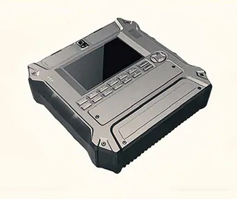
Thirty sets call for repeatable housing parts, but the program was still at the prototype stage. Vacuum casting in silicone molds offered a way to reproduce the plastic enclosure without committing to injection tooling at this point. It also allowed the customer to check the external design, assembly clearances and handling before deciding on a production process.
A well-prepared master is essential. Its surface condition, openings and edges carry through to the silicone mold and subsequent castings. We review the CAD model for wall transitions, ribs, bosses, access to internal features and surfaces that mate with other parts. We then define the master finish, mold split and any features that require additional attention during casting or trimming.
For 30 sets, mold life needs to be considered per housing component. The number of silicone molds depends on the geometry, resin and acceptable yield; it should be set during production planning rather than assuming one mold will make the entire order. First castings can be checked against the mating parts before the remaining sets are produced.
The enclosure material is ABS-like polyurethane casting resin, not injection-molded ABS. The distinction matters if the prototype must demonstrate a specific flame rating, chemical resistance or long-term mechanical performance. We would confirm those requirements and the appropriate test material before production.
Where the Housing Meets the Hardware
The main manufacturing challenge was keeping the mixed-material parts compatible. An attractive shell is of little use if a bracket cannot seat inside it or a moving component interferes with the enclosure.
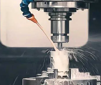
CNC-machined aluminum brackets provide the mounting geometry. We check their hole positions and contact faces against the housing design, especially where painted surfaces or cast features affect clearance.
Stainless steel and brass bushings are produced by turning. Bore size, outside diameter and any intended press or clearance fit are reviewed with the mating components. Inspection is based on the drawing's critical dimensions rather than treating all features as equally sensitive.
Stainless steel lead screws and plastic nuts form a functional pair. The screw is made using turn-mill machining; the nut's material and manufacturing route follow its drawing and use conditions. Thread geometry, lead, clearance and travel must be considered together. Where a running test is required, the customer can specify the expected load and motion so the prototype can be assessed for its intended purpose.
Across approximately 25 part designs, we track the revision and required quantity for each item. A trial fit identifies conflicts before cosmetic finishing or packing all 30 sets. The scope of any final assembly check is agreed with the customer from the available drawings and components.
Painting and Screen Printing the Appearance Parts
The visible housing components are finished to the customer's color, sheen and artwork requirements. Before painting, we identify mating faces, screw locations and other areas where coating thickness could affect assembly. The print position and artwork are confirmed against an approved reference.
After surface preparation and finishing, we inspect the appearance of the housings and check representative parts with the hardware. This links the cosmetic result to the mechanical purpose of the prototypes: the painted and printed enclosure must still fit the components it was made to hold.
Request a Quote for a Multi-Part Prototype Set
Send us the housing CAD files, drawings for the machined components, a bill of materials and an assembly view if available. For an accurate quotation, identify the quantity of each part per set, critical fits, nut and lead screw specifications, color and print references, and any tests the prototypes need to support.
YS Rapid provides custom vacuum casting for electronics housings alongside CNC machining, turning, turn-mill machining and finishing. Share your files and requirements, and we can review the production approach for the complete prototype set.
 EN
 jp
 ko
 fr
 de
 es
 it
 pt
 tr
 ar
 iw