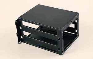
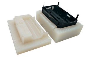
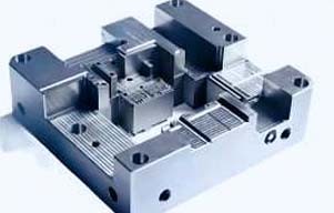
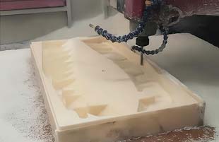
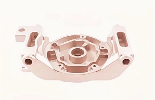
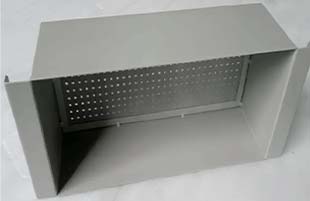
Rapid injection molding helps product teams move from early prototypes to production-representative plastic parts without immediately committing to a full-scale production mold. It is especially useful when a design is stable enough for tooling and the project needs hundreds or several thousand molded parts for validation, bridge production, or launch.
Rapid tooling follows the normal injection-molding cycle but is optimized for shorter lead time and lower initial investment than conventional high-volume tooling.
What Is Rapid Injection Molding?
Rapid injection molding is a shortened-tooling manufacturing method used to produce plastic parts from a dedicated mold for prototypes, bridge production, and lower-volume manufacturing.
It gives engineers access to production-relevant thermoplastics without immediately investing in long-life tooling. For projects beyond one-off samples, china rapid injection molding can help validate fit, assembly, material behavior, and repeatability before larger production quantities.
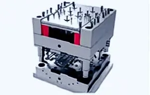
When Does Rapid Injection Molding Make Sense?
Rapid injection molding makes sense when the design is reasonably stable and the required quantity is high enough that repeated CNC machining or 3D printing becomes inefficient.
| Approximate Quantity | Process Often Worth Evaluating |
|---|
| 1–20 parts | CNC machining or 3D printing |
| Tens to hundreds | CNC, casting, or rapid molding |
| Hundreds to several thousand | Rapid injection molding |
| Large repeat volumes | Production injection molding |
These ranges are planning references because part size, resin, geometry, and tooling complexity can shift the break-even point.
Rapid molding becomes particularly valuable when engineers need actual molded material behavior, repeated assembly testing, or enough components for pilot builds.
How Does Wall Thickness Affect Part Quality?
Wall thickness is the nominal section thickness through which molten polymer flows and later cools inside the mold.
Uniform wall thickness generally helps reduce uneven cooling, sink marks, and warpage. Many molded plastic components use nominal walls in the approximate 1–3 mm range, although the correct thickness depends strongly on resin and product function.
Where extra stiffness is needed, ribs are usually preferable to making isolated sections much thicker. Gradual transitions between different thicknesses can also help avoid abrupt changes in cooling behavior.
Why Is Draft Important?
Draft angle is the slight taper added to surfaces parallel to the mold-opening direction so the cooled part can be released more easily.
A draft of roughly 0.5–2° per side can be a useful starting point for many smooth surfaces. Textured surfaces and deep features may require additional draft.
Draft should be included during CAD development. Zero-draft walls can increase ejection force, create surface scuffing, and make mold construction more difficult.
The exact value should therefore be confirmed during DFM rather than applied as one fixed rule to every feature.
How Do Undercuts Affect Tooling Cost?
An undercut is a feature that prevents a molded component from being removed directly along the main mold-opening direction.
Undercuts may require slides, lifters, or other moving mold components. These mechanisms add tooling complexity, maintenance needs, and manufacturing cost.
Designers should check whether side holes or recessed features can be redesigned to simplify the mold. In some cases, changing the parting line or modifying snap geometry can remove a side action without affecting the product's function.
Rapid Injection Molding vs CNC Machining vs 3D Printing
Process comparison determines whether tooling investment is justified by material requirements, quantity, and design maturity.
| Factor | Rapid Injection Molding | CNC Plastic Machining | 3D Printing |
|---|
| Dedicated mold | Yes | No | No |
| Production resin | Yes | Stock material | Process-dependent |
| Design changes | Moderate | Easy | Very easy |
| Very low quantity | Moderate | Excellent | Excellent |
| Repeat quantity | Excellent | Moderate | Limited |
| Molded surface details | Excellent | Limited | Process-dependent |
Early development can therefore use china plastic cnc machining before the design is stable enough for molding. This staged approach lets engineers verify dimensions and assembly without investing in a mold too early.
Once the geometry is validated and quantity increases, rapid molding can provide more realistic data about shrinkage, ejection, surface appearance, and repeatability.
What Determines Rapid Injection Molding Cost?
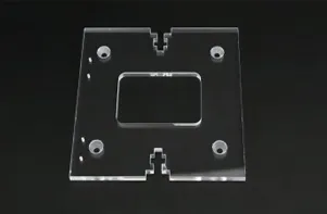
Rapid injection molding cost is mainly determined by mold complexity, part size, resin, cavity count, surface finish, tolerance, and expected production quantity.
A simple two-part mold generally costs less than a tool requiring multiple sliders or complex side actions. Demanding cosmetic textures and very tight tolerances can also increase tooling and process-control requirements.
The mold should be evaluated as part of total project cost because higher tooling investment may still reduce unit cost over the planned quantity.
Part consolidation can also change the calculation. One well-designed molded component may replace several machined or assembled parts, reducing downstream assembly operations.
When Should Silicone Molding Be Considered?
Silicone molding is a manufacturing route for flexible elastomer components that require different mechanical behavior from rigid thermoplastics.
Seals, pads, soft covers, flexible interfaces, and similar parts may be better suited to silicone processes. For such applications, low volume silicone molding can be considered when flexibility, compression behavior, or heat resistance is more important than rigid structural performance.

Selecting the material family first helps avoid an unsuitable molding process.
Engineers should therefore define hardness, flexibility, temperature exposure, sealing requirements, and expected service conditions before choosing between thermoplastic injection molding and silicone processing.
What Should Be Included in a Rapid Molding RFQ?
A rapid molding RFQ is the technical package used to evaluate manufacturability, tooling requirements, price, and lead time.
Provide a 3D model, 2D drawing, resin, color, quantity, expected production volume, critical tolerances, surface requirements, and cosmetic areas. It is also useful to state whether the tool is intended for validation, bridge production, or recurring orders.
YS Rapid can use this information during DFM review to identify draft, wall-thickness, parting-line, and undercut issues before tooling begins.
FAQ About Rapid Injection Molding
Rapid injection molding FAQs answer common design and purchasing questions before low-volume tooling is ordered.
1. Is rapid injection molding suitable for prototypes?
Yes. It is useful when prototypes must use production-relevant thermoplastics and closely represent molded production parts.
2. How many parts justify rapid injection molding?
There is no universal quantity. It often becomes attractive from hundreds to several thousand parts, but geometry and resin can shift the break-even point.
3. How much draft should a molded part have?
Around 0.5–2° per side is a useful starting range for many smooth surfaces, while textured or deep walls may need more.
4. Why is uniform wall thickness important?
More uniform walls help reduce uneven cooling, sink marks, internal stress, and warpage.
5. Can undercuts be injection molded?
Yes, but they may require slides, lifters, or other mold mechanisms that increase tooling complexity and cost.
6. When should CNC machining be used before molding?
CNC machining is useful when the design is still changing or only a small number of functional plastic parts are needed.
Conclusion
Rapid injection molding is most effective when a product has moved beyond early prototyping but is not yet ready for conventional high-volume tooling. The best results come from aligning quantity, material, wall thickness, draft, tolerance, and tooling complexity before mold construction begins.
By applying DFM early, product teams can reduce unnecessary side actions, avoid difficult geometry, and select a process that fits both technical and commercial goals.
YS Rapid supports rapid tooling and low-volume plastic part manufacturing for customers moving from prototype validation toward repeat production.
References / External Resources
ISO 20457:2026 – Plastics Moulded Parts — Tolerances and Acceptance Conditions
https://www.iso.org/standard/90304.html
Protolabs – Plastic Injection Molding Design Guidelines
https://www.protolabs.com/services/injection-molding/plastic-injection-molding/design-guidelines/
Injection Moulding – Wikipedia
https://en.wikipedia.org/wiki/Injection_moulding
 EN
EN
 jp
jp  ko
ko  fr
fr  de
de  es
es  it
it  pt
pt  tr
tr  ar
ar  iw
iw