This CNC prototyping project involved ten complete prototype sets of a compact electronic product for a customer in the United States. Each unit contained approximately 12 custom components made from PC, aluminum alloy and stainless steel.
The PC and aluminum parts were manufactured by CNC machining, while the stainless steel components required turn-mill machining. After machining and trial assembly, the visible enclosure parts were spray-painted and the customer’s logo was applied by screen printing.
For this electronic product prototype, the main challenge was coordinating different materials, manufacturing processes and surface finishes within one assembly. The individual parts needed to fit correctly before and after painting, with consistent enclosure gaps and properly aligned openings.
Electronic Product Prototype Overview
Project item | Details |
Product | Compact electronic product enclosure |
Customer market | United States |
Quantity | 10 complete prototype sets |
Parts per set | Approximately 12 custom components |
Materials | PC, aluminum alloy and stainless steel |
Manufacturing | CNC milling and turn-mill machining |
Finishing | Spray painting |
Logo | Screen printing |
Project scope | DFM review, machining, fit checking, finishing, inspection and packaging |
Reviewing the Complete Prototype Assembly
The customer supplied 3D CAD files, 2D drawings and appearance requirements. Before production, our engineering team reviewed both the individual components and the complete product assembly.
The review covered machining access, wall thickness, internal cavities, connector openings, fastening features and visible surfaces. We also examined how the PC, aluminum and stainless steel parts would locate and connect during assembly.
Particular attention was given to:
· Alignment between the upper and lower enclosures
· Locations of connector and control openings
· Screw holes and locating features
· Fit between plastic and metal components
· Clearance for internal parts
· Visible gaps around the enclosure
· Surfaces requiring protection during painting
· The effect of paint thickness on final fit
Reviewing these details before machining helped reduce the risk of discovering interference, misalignment or uneven gaps during final assembly.
CNC Machining the PC Enclosure Parts
Several enclosure components were CNC machined from solid polycarbonate material.
PC is often used for functional electronic enclosure prototypes because it offers good impact resistance and practical mechanical properties. For a requirement of ten sets, CNC plastic machining allowed the customer to obtain custom components without investing in injection mold tooling.
However, PC must be machined carefully. Excessive cutting heat or internal material stress may cause deformation, cracking or surface marks, particularly around thin walls and detailed features.
During machining, we paid close attention to the enclosure walls, internal pockets, connector openings, locating details and visible edges. The machining sequence was planned to maintain part stability as material was removed.
After CNC machining, the PC parts were deburred and inspected. Because the visible components would later be painted, their surfaces were also checked for scratches and machining marks that could affect the final cosmetic appearance.
CNC Machining the Aluminum Components
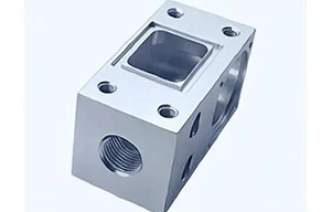
The aluminum alloy components contained structural and appearance-related features. These parts were also manufactured by CNC machining.
Rather than checking only the overall dimensions of each part, we focused on the features that influenced the complete assembly. These included mating surfaces, hole positions, locating steps, fastening points and external edges.
The aluminum parts had to align with both the PC housings and the stainless steel components. A small difference in a hole or locating feature could affect the position of an opening or create an uneven gap in the finished enclosure.
For this reason, the aluminum components were inspected individually and then test-fitted with their corresponding parts.
Turn-Mill Machining the Stainless Steel Parts
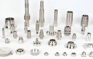
The stainless steel parts combined cylindrical profiles with milled features. Turn-mill machining was selected to produce these components.
This manufacturing route was suitable for parts that required turned diameters together with flats, holes, slots or other non-rotational details. It also helped maintain the positional relationship between features while reducing unnecessary setups.
After machining, the stainless steel parts were deburred, dimensionally inspected and checked with the related PC and aluminum components.
Trial Assembly and Fit Checking
The first trial assembly was completed before the parts entered the final surface-finishing stage.
Fit checking at this point was important because spray painting adds material to the surfaces. If the unpainted components already fitted too tightly, the coating thickness could cause interference during final assembly.
The trial assembly checked:
· Alignment of the upper and lower housings
· Fit between PC, aluminum and stainless steel parts
· Consistency of visible enclosure gaps
· Alignment of holes and external openings
· Installation of screws and fasteners
· Interference between mating components
· Overall appearance and handling of the device
If a fitting issue was identified, the relevant component or machining data could be adjusted before painting. This reduced the possibility of reworking finished parts or damaging the cosmetic surfaces.
Once the initial assembly was confirmed, production of the remaining components continued using the verified machining data.
Spray Painting and Logo Printing
After machining and trial assembly, the visible enclosure components were prepared for spray painting.
The surfaces were cleaned and inspected before coating. Areas affecting assembly were protected where necessary, particularly around holes, edges, fastening features and mating surfaces.
After painting, the parts were examined for color consistency, smooth coverage, dust, scratches and excessive coating buildup. The appearance needed to remain consistent across all ten prototype sets.
The customer’s logo was then applied by screen printing. Its position, orientation and clarity were checked against the supplied artwork. Accurate logo placement was important because it directly influenced the presentation of the finished electronic product.
Final Assembly and Prototype Inspection
Following surface finishing, the components were assembled again for final verification.
Inspection included both dimensional fit and cosmetic appearance. We checked that the parts could be assembled without interference, the external openings remained aligned and the enclosure gaps were reasonably consistent.
The final inspection also covered:
· Completeness of each prototype set
· Fastener and connector positions
· Painted surface quality
· Logo position and print clarity
· Scratches or damage from assembly
· Overall appearance of the finished product
The components were individually protected during packaging to reduce the risk of rubbing or cosmetic damage in transit. All ten prototype sets were then prepared for shipment to the customer in the United States.
Supporting Electronic Product Development
Electronic product prototyping often involves more than machining a single plastic enclosure. One product may combine CNC-machined plastic housings, aluminum structures, stainless steel components, surface finishes and printed graphics.
Coordinating these elements through one prototype project can make it easier to identify manufacturing and assembly issues before tooling or production begins.
YS Rapid supports custom electronic product development with CNC prototyping, plastic and metal machining, turn-mill machining, surface finishing, logo printing, fit checking and prototype assembly.
To request a quotation, please provide your 3D CAD files, 2D drawings, material requirements, surface finish specifications, required quantity and relevant assembly information. Our team will review the project and recommend a suitable manufacturing route.
 EN
EN
 jp
jp  ko
ko  fr
fr  de
de  es
es  it
it  pt
pt  tr
tr  ar
ar  iw
iw