Reviewing the Complete Product Before Manufacturing
The customer provided 3D CAD files, 2D drawings, a BOM and assembly information. Because the device contained different materials and manufacturing processes, we reviewed it as a complete assembly instead of treating every component as an independent part.
Our engineering review focused on:
· Suitable manufacturing methods for each component
· Critical fits between the housings and internal parts
· Alignment of buttons, gears and mounting features
· Clearance around moving components
· Assembly sequence and fastening access
· Cosmetic requirements for visible surfaces
· Dimensions that could affect product function
This review helped identify potential interference and assembly risks before manufacturing began. It also allowed the customer to manage the project through one rapid prototyping service rather than coordinating several suppliers separately.
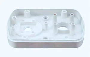
CNC-Machined PC and ABS Housings
The main housings were made from PC and ABS. As only 20 sets were required and the design still needed testing, CNC machining was selected instead of production injection molding.
CNC prototyping allowed the customer to obtain functional plastic enclosures without investing in injection mold tooling. It also provided greater flexibility if the housing design needed to be modified after testing.
The housings contained external openings, internal pockets, mounting features and mating surfaces. Careful machining was required around thin walls, screw positions and narrow edges to reduce deformation and maintain a consistent fit.
After machining, the housings were checked for:
· Alignment between upper and lower sections
· Consistent gaps around visible joints
· Location of display and button openings
· Clearance for internal components
· Screw-hole and mounting-point alignment
· Overall dimensions and external appearance
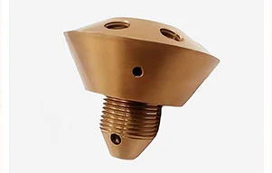
CNC-Machined Aluminum Functional Parts
Several internal functional components were produced from aluminum alloy by CNC machining. These parts supported the internal structure and located other mechanical components inside the device.
Mounting holes, locating features and mating surfaces were inspected according to the drawings. Where required, the aluminum parts were anodized to improve surface protection and provide a clean finished appearance.
The parts were also installed in the plastic housings during trial assembly. This ensured that the internal structure could be assembled correctly without forcing the parts or affecting the external housing fit.
Precision Brass Gears
The device included small brass gears used in its internal mechanism. Brass offered good machinability and was suitable for producing the required gear features and precision bores.
The gears were inspected for tooth condition, bore dimensions and fit with their mating shafts and components. Their movement was then checked within the assembled mechanism.
This functional check was important because small dimensional variations across several parts can accumulate and affect gear engagement or operating smoothness.
Vacuum-Cast Silicone Buttons
The silicone buttons needed to match the housing openings and provide suitable flexibility during operation. For 20 prototype sets, vacuum casting with prototype tooling offered a practical solution without requiring production compression mold tooling.
The completed silicone buttons were evaluated together with the corresponding housings and internal contact points. We checked:
· Button position and spacing
· Fit within the housing openings
· Exposed button height
· Pressing movement and return
· Surface appearance
· Interference with surrounding parts
A silicone button may meet its individual dimensions but still feel incorrect after installation. For this reason, its fit and movement were evaluated as part of the complete assembly.
Stainless Steel Sheet Metal Components
Several internal brackets and functional parts were manufactured from stainless steel sheet metal. The process included cutting, bending, forming and deburring according to the individual part requirements.
Bend locations and mounting holes had to align with the CNC-machined housings and aluminum parts. Burrs and sharp edges were removed to prevent damage to nearby plastic and silicone components during assembly.
The finished sheet metal parts were inspected for overall dimensions, bend angles, flatness and installation position.
Painting and Cosmetic Inspection
The CNC-machined PC and ABS housings required a clean, professional appearance for customer evaluation. After machining, the visible surfaces were sanded, prepared and painted in the customer’s specified color.
Surface preparation was carefully controlled because machining marks, scratches or uneven sanding can remain visible after painting. Before assembly, the finished housings were inspected for:
· Color consistency
· Scratches, dents and surface marks
· Dust or contamination
· Uneven paint coverage
· Visible sanding lines
· Paint buildup around openings
· Defects near edges and corners
Approved housings were protected throughout assembly to reduce the risk of cosmetic damage.
Trial Assembly and Final Fit Checking
With approximately 28 different components in each unit, dimensional inspection of individual parts was not enough. The complete device also required fit checking and assembly verification.
We first completed a trial assembly to verify the housing fit, internal mounting positions, silicone button response, gear movement and sheet metal alignment. Any fitting issues could then be addressed before assembling all 20 units.
Final inspection covered:
· Component completeness
· Housing alignment and external gaps
· Button movement and return
· Gear engagement and mechanical movement
· Screw and mounting-point alignment
· Protection of painted surfaces
· Overall assembly condition
The completed prototypes were cleaned and packed individually before shipment to Canada.
One Rapid Prototyping Service for a Complete Product
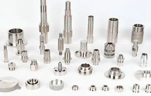
This project combined CNC plastic machining, aluminum machining, brass gear production, silicone vacuum casting, stainless steel fabrication, painting and assembly inspection.
When comparing rapid prototyping companies, customers developing multi-part products should consider more than individual part prices. Process coordination, fit checking and responsibility for the complete assembly can be equally important.
YS Rapid provides fast prototyping for medical, diagnostic, laboratory and electronic equipment. We help customers move from CAD files to complete physical prototypes through one coordinated project team.
For a new project, customers can provide 3D CAD files, 2D drawings, a BOM, material requirements, estimated quantities and assembly information. Our team will review the design and recommend a suitable route for prototype manufacturing, finishing, inspection and delivery.
 EN
EN
 jp
jp  ko
ko  fr
fr  de
de  es
es  it
it  pt
pt  tr
tr  ar
ar  iw
iw