Planning the Prototype Around the Assembly
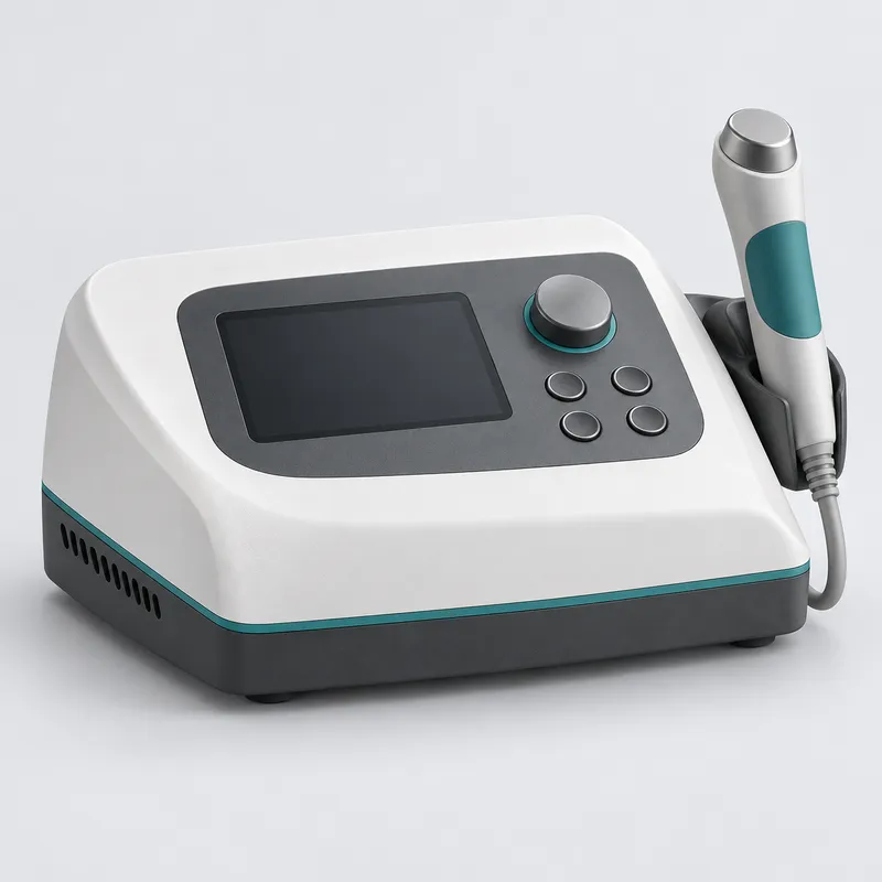
The product design included a two-piece enclosure, an inclined control panel, a display window, a rotary control, silicone buttons and a side-mounted handpiece.
Before machining began, we compared the individual part drawings with the complete assembly drawing. This allowed us to identify the dimensions that affected more than one component.
The most important interfaces included:
· The joint between the upper housing and lower base
· The PC lens and its surrounding display opening
· The silicone buttons and internal control positions
· The aluminum structure and plastic mounting points
· The stainless steel turned parts and mating holes
· The handpiece holder and the side of the enclosure
· Internal space for fasteners, cables and connected components
By reviewing these relationships before production, we could apply closer control to the features that directly influenced product fit and operation.
CNC Prototype Machining of the ABS Enclosure
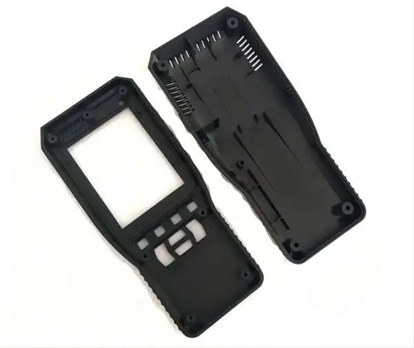
The upper housing and lower base were CNC machined from ABS. For 30 prototype sets, CNC machining provided a practical way to produce functional enclosures without committing to injection mold tooling.
It also allowed the customer to test the physical design and make changes more easily before moving toward production.
The upper housing formed the main visual surface of the device. It incorporated the inclined control area, display opening, button locations, ventilation details and mounting features for the handpiece holder.
Large plastic housings can deform as internal material is removed. The machining sequence and workholding method were therefore planned to maintain stability around deep pockets, thin sections and external edges.
Particular attention was given to the mating edges, screw positions and control openings because these areas directly affected the final assembly.
Fitting the PC Display Lens
A CNC-machined PC lens was installed over the display area. Its outer profile needed to match the opening in the ABS housing and produce an even, controlled perimeter gap.
PC is suitable for transparent functional prototypes, but it must be machined and handled carefully. Excessive cutting heat, unsuitable clamping pressure or poor handling can result in deformation, edge damage or visible scratches.
After machining, the lens was checked in its installed position rather than evaluated only as an individual component. We inspected its alignment, edge condition and relationship with the surrounding control panel.
The lens surface was protected during handling and assembly to help maintain its appearance.
CNC-Machined Aluminum Housing and Brackets
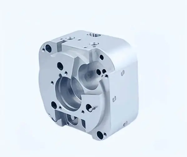
A CNC-machined aluminum housing and several aluminum brackets formed the internal support structure of the device.
These parts located the internal components and connected them to the ABS enclosure. Critical holes, shoulders and locating surfaces were machined according to the 2D drawings.
During the initial assembly, we verified that the aluminum components could be installed in the correct sequence and that their mounting holes aligned with the plastic enclosure.
We also checked the available space around the brackets, fasteners and cables. This was important because a part can match its drawing but still be difficult to install if tool access or assembly direction has not been considered.
Precision Stainless Steel Turned Parts
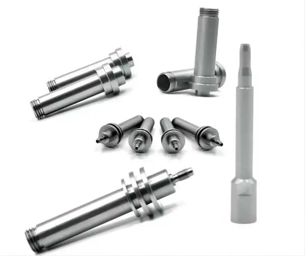
Several cylindrical stainless steel components were produced by CNC turning. These parts required controlled diameters, lengths and shoulder positions to fit the corresponding aluminum components.
The turned parts were inspected according to the drawing requirements and then installed in the internal assembly. This physical fit check helped confirm that they provided the intended positioning or movement without excessive clearance or assembly resistance.
For mating components, small dimensional variations across several parts can accumulate. Checking the actual assembly therefore provided useful information beyond individual measurement results.
Silicone Buttons for the Control Panel
The control panel also contained custom silicone buttons. These components were produced using low-volume prototype tooling suitable for the required quantity.
The silicone buttons needed to match both the external openings in the ABS housing and the internal contact positions. Their performance was evaluated after installation in the control panel.
We checked whether the buttons remained centered, maintained a consistent exposed height and returned normally after being pressed. This helped identify any interaction between the silicone components, housing openings and internal mounting structure.
First Assembly and Interface Verification
Before completing all 30 units, the first set was assembled to verify the main interfaces across the product.
The internal aluminum structure and stainless steel parts were installed first. The PC lens and silicone buttons were then fitted into the upper enclosure, followed by the housing sections and handpiece holder.
This first build allowed us to check:
· Housing closure and external gaps
· Display lens position
· Alignment of controls
· Button movement and return
· Internal mounting positions
· Fit of turned components
· Handpiece placement
· Assembly sequence and fastener access
Once the main assembly relationships were confirmed, the approved requirements were applied to the remaining units.
Consistency Across 30 Prototype Sets
Producing one successful prototype is different from producing 30 consistent assemblies. Part organization, in-process inspection and controlled assembly were required throughout the order.
The completed units were compared for housing alignment, control position, button response, lens fit and overall appearance. Visible surfaces were protected during assembly, and each unit was checked for completeness before packing.
This approach helped the customer receive a repeatable low-volume build rather than 30 individually fitted samples.
CNC Prototype Manufacturing Service from YS Rapid
This project combined plastic CNC machining, aluminum machining, precision turning, silicone prototype production and complete assembly checking.
YS Rapid provides CNC prototype manufacturing services for medical, diagnostic, laboratory, electronic and other equipment projects. We focus on the finished product as well as the individual components, especially when an assembly contains different materials and manufacturing processes.
Customers can provide 3D CAD files, 2D drawings, a BOM, material requirements, quantities and assembly information. Our team will review the complete project and recommend a suitable route for functional prototypes and low-volume manufacturing.
 EN
EN
 jp
jp  ko
ko  fr
fr  de
de  es
es  it
it  pt
pt  tr
tr  ar
ar  iw
iw