Where Assembly Risk Exists on This Component
Instead of treating every dimension with the same priority, we first identify the features that could stop assembly or change the installed position.
Interface Area | Possible Assembly Problem | Manufacturing Response |
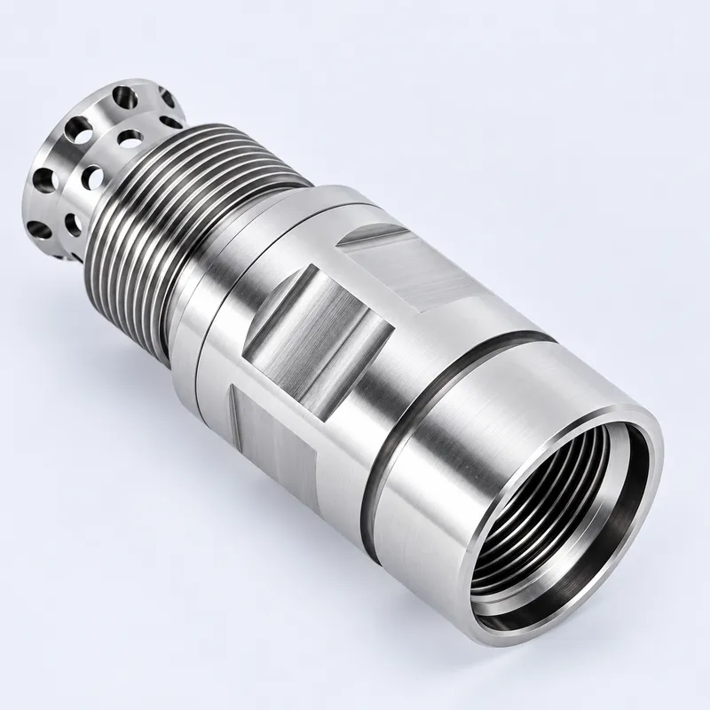
Internal thread | Mating part binds or cannot reach its seated position | Control thread form, entry, depth, and the shoulder behind the thread |
External thread | Inconsistent engagement or damaged thread start | Monitor tooling, deburr the lead, and protect the thread during handling |
Turned shoulders | Incorrect axial location after tightening | Machine and inspect shoulder distances from the drawing datum |
Side pockets and flats | Tool or mating feature is misaligned | Maintain angular orientation from a controlled machine reference |
Radial openings | Internal burrs or restricted passage | Control breakthrough and deburr intersecting edges carefully |
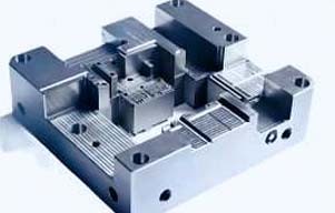
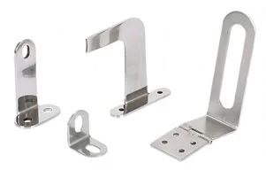
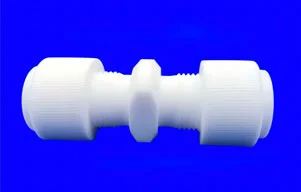
Related CNC parts | Each part passes, but the set does not assemble | Review shared interfaces and carry out agreed fitting checks before shipment |
Why the Geometry Suits Turn-Mill Production
The main body, concentric diameters, grooves, faces, and threads are rotational features. The side pockets, flats, and circumferential hole pattern are not. Turn-mill machining brings these two feature groups into one coordinated route.
The setup still depends on tool access and the drawing. Its value is keeping the primary turning datum connected to live-tool operations, limiting alignment errors when a partially finished component moves between unrelated turning and milling setups.
The radial features must sit in the intended position around the threaded body, while the milled sections remain correctly located from the functional shoulders.
303 Stainless Steel Supports a Feature-Dense Machining Route
The customer specified 303 stainless steel. Its machinability suits a component requiring turning, internal and external threading, grooving, drilling, and milling. Effective chip formation supports consistent production across the 100-piece run.
303 is not a universal substitute for other stainless grades. Material choice must follow the drawing and service conditions.
Managing the Other CNC Parts in the Same Project
A multi-part order may involve different machines, cycle times, materials, and finishes, yet all parts must arrive together and work together.
YS Rapid organizes the project by part number and drawing revision while marking shared interfaces. CNC turning may suit one item, turn-mill machining another, and multi-axis milling a related housing. Schedules and accepted quantities are then coordinated at project level.
This one-stop CNC machining approach provides one contact for technical questions, revision updates, production status, inspection, and delivery. It also keeps responsibility for cross-part fit from being divided among unrelated suppliers.
How We Release a Coordinated Part Set
The release plan is based on the customer’s files and agreed requirements. It can include:
1. Confirming that the 2D drawing and 3D model describe the same revision
2. Identifying the internal and external thread specifications before tooling is assigned
3. Marking mating diameters, shoulders, clearances, and orientation-sensitive features
4. Inspecting the first completed component before continuing the full 100-piece run
5. Monitoring selected functional dimensions during production to detect tool wear
6. Removing burrs from thread starts, cross holes, and milled intersections
7. Comparing related parts through dimensional correlation or an agreed fit check
8. Identifying and packing the different part numbers for efficient receiving and assembly
9. Inspection follows the drawing. Any mating sample, specific thread gauge, inspection report, or trial-assembly requirement should be included with the RFQ.
What an R&D Engineer Can Send for Review
Send STEP files and dimensioned drawings for the complete part package when possible, together with material grades, quantities, threads, critical tolerances, finishes, and target delivery date. An assembly view helps identify dimensions connected across separate drawings.
YS Rapid can quote the threaded turn-mill component alone or coordinate the related custom CNC parts as one project. We will review the interfaces, select a practical process for each part, and identify questions that should be resolved before production begins.
 EN
EN
 jp
jp  ko
ko  fr
fr  de
de  es
es  it
it  pt
pt  tr
tr  ar
ar  iw
iw