Keeping the Bore, OD, and Hole Pattern on One Datum
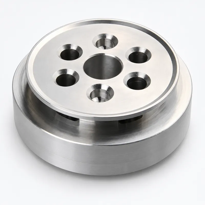
The main body is rotationally symmetrical, so CNC turning efficiently establishes the outside diameter, center bore, shoulder faces, and annular steps. Live tooling then drills and countersinks the holes on the front face while C-axis indexing controls their angular positions. The part remains held in the same chuck throughout these operations.
Our process planning starts by identifying which diameter or bore functions as the primary datum in the customer’s 2D drawing. The machining sequence is then built around that datum so the critical circular features are completed before the part is released. Avoiding a separate milling setup reduces the risk of reclamping error and helps preserve the relationship between the turned centerline and the face-hole pattern.
“One setup” does not mean that the component is produced with a single cutting operation. Turning, boring, facing, drilling, and countersinking remain separate tool movements. The advantage is that they are carried out on one turn-mill machine without transferring the part to another machine between the critical operations. This creates a more controlled route for a low-volume batch and supports consistent hole positions, countersinks, and edge breaks.
Material Choice: Aluminum 6061-T6
Aluminum 6061-T6 offers a useful combination of machinability, dimensional stability, relatively low weight, and corrosion resistance. It responds well to both turning and live-tool drilling when cutting parameters and tools are properly selected, making it practical for mounts, adapters, flanges, and other hardware used in optical instruments.
Using one specified temper also supports repeatability across the 50-piece batch. Tool offsets and inspection intervals can be managed around a consistent material condition, helping maintain bore size, shoulder position, hole pattern, and centerline relationships from the first part to the last.
Inspection Focused on Assembly Function
Concentricity cannot be confirmed by checking only one diameter with a caliper. Inspection must reflect how the component will locate and rotate in the final equipment. Depending on the drawing requirements, our checks may include:
· Center bore and outside diameter measurements
· Runout checks from the specified datum axis
· Shoulder height and face relationship inspection
· Hole position relative to the turned centerline, diameter, and countersink verification
· Visual inspection of machined surfaces and deburred edges
First-article inspection is used to verify the turn-mill setup before the full batch proceeds. In-process checks then help identify tool wear or offset drift before it affects multiple parts. Final inspection records can be prepared according to the project requirements. The exact concentricity or runout requirement and its datum must follow the customer’s 2D drawing rather than a general shop standard.
From 3D Model to Production-Ready Machining
The 3D model helps us understand the complete shape and evaluate tool access, while the 2D drawing defines the dimensions, datums, tolerances, surface requirements, and inspection priorities. When the two files are reviewed together, potential conflicts or unclear callouts can be raised before material is cut.
This drawing-based workflow is particularly valuable for optical equipment parts, where a feature that appears simple may control the position of another component in the assembly. Our engineers review the datum structure, turn-mill sequence, live-tool access, C-axis hole positions, and inspection method before releasing the job to production.
CNC Turning and Milling Support from YS Rapid
YS Rapid provides CNC turning services for optical equipment parts, prototypes, and low-volume precision components. When a design combines rotational geometry with face holes, radial holes, slots, flats, or threads, live-tool machining can often reduce the number of setups. Aluminum, stainless steel, brass, and engineering plastics can be supported, with deburring, surface finishing, inspection, and delivery coordinated through one project team.
The objective is not simply to reproduce the visible shape. We identify the dimensions and geometric relationships that determine whether the part will locate, align, and function correctly in the customer’s assembly. This approach suits optical instrument hardware, precision mounts, adapters, and other drawing-based components in which a shared centerline is functionally important.
Request a Quote for Optical Equipment Parts
Send your 3D model, 2D drawing, material specification, quantity, and inspection requirements to YS Rapid. We will review the datum structure, concentric features, live-tool access, and suitability for single-setup production before preparing a quotation and machining recommendation.
 EN
EN
 jp
jp  ko
ko  fr
fr  de
de  es
es  it
it  pt
pt  tr
tr  ar
ar  iw
iw