Why This Part Is Suited to Turn-Mill Machining
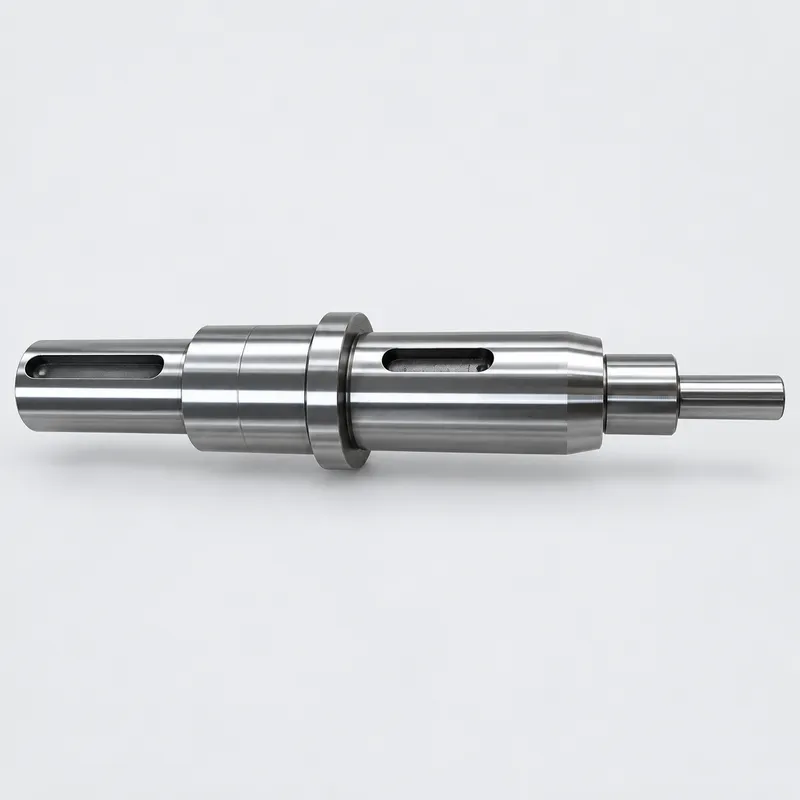
The round features are produced by turning, while the elongated side openings require milling at controlled axial and angular positions. Moving the shaft between unrelated turning and milling setups could add location error and handling time.
A turn-mill process allows the main diameters, shoulders, faces, and milled side features to be planned from a consistent datum structure. This is especially useful when a slot must align with a shoulder, flange, or another feature used during assembly.
A typical sequence includes:
1. Turning the main outside diameters, shoulders, faces, and reduced end sections.
2. Finishing the locating flange and other axial reference surfaces.
3. Indexing the part to mill the side slots or flats at the drawing-defined position.
4. Deburring without rounding functional edges or marking finished diameters.
5. Cleaning, inspecting, and protecting the parts for shipment.
The final process is established only after reviewing the actual drawing. Stainless steel grade, tolerance, surface finish, slot depth, edge-break requirement, and inspection scope can all affect tooling and cycle planning.
What We Check Before Releasing the First Article
Checking each dimension independently is not enough. The part must preserve the relationships required for assembly and operation.
Before batch production, the first article is checked for:
1. The size and sequence of the stepped diameters
2. Shoulder and flange locations along the shaft axis
3. Slot width, length, depth, and end radius
4. Axial position of each milled feature from the specified datum
5. Angular orientation where the drawing controls clocking
6. Burrs or sharp edges around the slot openings
7. Overall straightness, runout, or related geometric requirements when specified
This review confirms the machining and inspection methods. Any unclear datum, note, or feature relationship can be resolved before the full batch is produced.
Maintaining Consistency Across Approximately 1,000 Parts
During a longer stainless steel run, insert wear can shift a diameter, milling-tool wear can affect slot width, and trapped chips can damage a finished surface. Scheduled checks are used to identify these trends during production.
After first-article approval, selected critical dimensions are measured at defined intervals. Tool offsets are adjusted when measurement results begin moving toward a tolerance limit, and cutting tools are changed according to condition. Parts remain identified by production lot so inspection results can be connected to the applicable batch.
For repeat orders with the same drawing revision, the established setup and inspection history provide a controlled starting point.
Inspection Documentation for Incoming Quality Teams
Receiving and supplier-quality teams often need evidence that the agreed drawing characteristics were checked before shipment.
YS Rapid prepares a final dimensional inspection report covering the characteristics agreed during order review. The report can identify:
1. Customer part number and drawing revision
2. Purchase order or production-lot reference
3. Manufactured and inspected quantities
4. Nominal dimensions, tolerances, and recorded results
5. Inspection date and approval status
6. Material documentation when requested and agreed
Equipment is selected according to the characteristic and tolerance. Inspection may use micrometers, calipers, height gauges, pin gauges, or optical measuring equipment. Full inspection, customer report formats, material certification, or other documents should be requested with the RFQ so the workload can be included in the quote.
Export Packing That Protects Functional Surfaces
Shafts can pass inspection and still be damaged in transit. Reduced ends, flange faces, slot edges, and finished diameters are protected or separated as appropriate. Labels can match the required purchase order, part number, quantity, and lot identification.
A Practical RFQ Package Produces a More Accurate Quote
This is a custom-machined part, not a catalog shaft. Price and lead time depend on the drawing, material, inspection scope, and quantity.
For an accurate quotation, please provide:
1. A STEP file or other 3D CAD model
2. A dimensioned 2D drawing with tolerances and datums
3. The required stainless steel grade
4. Batch quantity and estimated repeat demand
5. Critical or fit-related dimensions
6. Surface-finish and edge requirements
7. Required inspection report, material documents, or customer templates
8. Delivery destination and requested schedule
If a mating component controls the slot or shaft fit, identify the relevant dimensions. This helps us quote the functional requirements rather than the outside shape alone.
Request a Quote for Stainless Steel Turn-Mill Machining
Need a reliable source for custom stainless steel shafts with turned diameters and side-milled features? Send your drawing package to YS Rapid. We will review the manufacturability, identify open technical questions, define the appropriate inspection scope, and quote the part according to its actual production requirements.
 EN
EN
 jp
jp  ko
ko  fr
fr  de
de  es
es  it
it  pt
pt  tr
tr  ar
ar  iw
iw