Specifications of Production Control for 50 Matching Fixtures
One approved sample does not automatically guarantee 50 matching parts. For this order, repeatability depended on keeping the same datum strategy, workholding method, tool sequence, and inspection points throughout production.
Feature | Manufacturing concern | Control method |
Precision locating bores | Size drift and positional error | Finish machining from established datums and interval inspection |
Bottom mounting face | Flatness and fixture stability | Controlled finishing after major pocket removal |
Open frame and internal windows | Distortion after roughing | Balanced stock removal and retained finishing allowance |
Threaded and counterbored holes | Assembly interference | Thread and depth checks during production |
Side holes | Alignment with top features | Consistent workholding and datum transfer |
Depending on the drawing requirements, the finished features can be verified with calibrated plug gauges, bore gauges, height gauges, or a coordinate measuring machine (CMM). Inspection records focus on the dimensions that influence locating and assembly rather than treating every dimension as equally critical.
Reading the Part as a Locating System
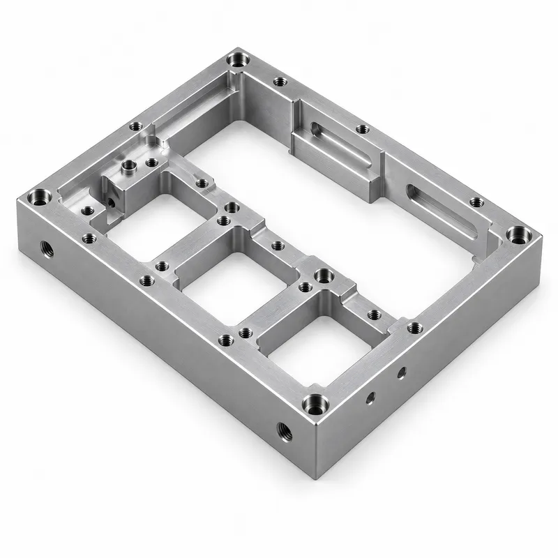
The visible frame provides support, but the fixture performs its function through a smaller group of related features. The bottom mounting surface establishes how the fixture sits on the machine. The precision bores locate mating components. Threaded and counterbored holes secure the assembly, while side holes connect the fixture with surrounding equipment.
These features were reviewed as one locating system rather than as separate dimensions. Before programming, the 3D model and 2D drawing were used to confirm:
· The primary mounting datum
· Which holes were used for locating rather than fastening
· The required bore tolerance and position
· Relationships between top and side features
· Areas where wall movement could affect final alignment
This distinction matters in fixture CNC machining. A clearance hole and a locating bore may appear similar in the CAD model, but they require different machining and inspection priorities.
Three Risks That Could Affect the Finished Fixture
Frame Movement After Material Removal
Large internal cut-outs leave long walls and narrow connecting sections. Removing the pockets too aggressively can release material stress and cause the frame to move.
Rough machining was therefore balanced across the part, with finishing stock retained on functional surfaces until the structure became stable.
Bore Variation During a 50-Piece Run
A tolerance of 0/+0.05 mm offers limited room for tool wear, heat, and cutting variation. The critical holes were not treated as ordinary drilled features. They were brought to size during the finishing stage, after the locating surfaces had been established.
Bore measurements were taken at planned intervals so that tool offsets could be corrected before a dimensional trend reached the tolerance limit.
Misalignment Between Different Faces
The fixture includes top features and side holes that must work together after assembly. Workholding and datum transfer were planned around their functional relationship.
This reduced the risk of producing individually acceptable features that did not align when the fixture was mounted to the automation system.
6061-T6 for a Lightweight, Machinable Fixture
6061-T6 is frequently selected for jigs and fixtures because it machines cleanly, provides useful rigidity, and keeps the finished assembly lighter than a comparable steel structure. It is also suitable for drilling, tapping, precision boring, and machining detailed pockets in a single component.
For automation equipment, lower weight can make fixture installation, adjustment, and replacement easier. The material is also compatible with common protective finishes when corrosion resistance or a particular surface appearance is required.
From a Rapid CNC Prototype to a 50-Piece Batch
YS RAPID supports both early fixture trials and low-volume production. A customer may first use our rapid CNC prototype service to confirm mounting points, access space, or component loading. Once the design is approved, the same drawing-controlled process can be used for a batch such as these 50 aluminum fixtures.
Our CNC machining services cover custom locating plates, assembly jigs, checking fixtures, robotic tooling, equipment frames, and other parts made from customer CAD data. This aluminum CNC machining service can combine milling, drilling, tapping, precision boring, multi-face machining, finishing, and inspection within one project.
For an accurate quotation, send the 3D file together with the 2D drawing and clearly identify the locating datums, critical holes, tolerance direction, inspection requirements, and required quantity. This information allows us to plan the fixture CNC machining process around how the part will actually function in your equipment.
 EN
EN
 jp
jp  ko
ko  fr
fr  de
de  es
es  it
it  pt
pt  tr
tr  ar
ar  iw
iw