What Had to Remain Consistent Across Big Batch Parts
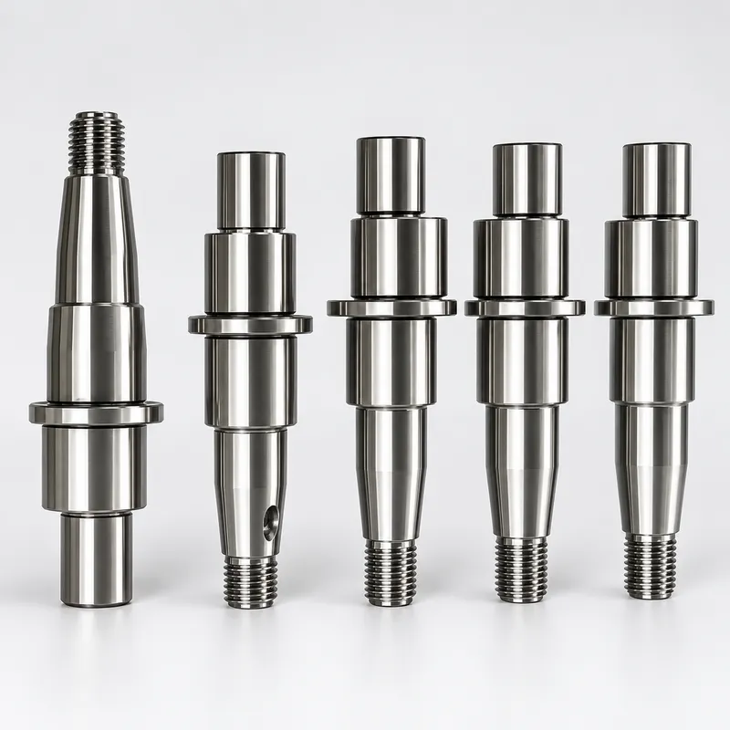
The visible shape of the shaft is relatively straightforward. The manufacturing challenge lies in repeating its functional geometry over the full batch.
The production plan focused on five relationships.
01 — Eccentric offset: The specified distance between the eccentric journal and the main axis.
02 — Fit diameters: The journal sizes used with bearings or bushings.
03 — Axial location: The distance between the shoulders and flange faces.
04 — Feature orientation: The angular relationship between the radial hole or flat and the eccentric section.
05 — Thread transition: The external thread, its effective length and the run-out near the adjoining shoulder.
These items were reviewed against the drawing datums before programming. This allowed the workholding, machining sequence and inspection stages to be based on how the shaft functions in the assembly, rather than treating each dimension independently.
Combining Turning and Live-Tool Machining
The concentric sections were turned to establish the main datum diameters, flange faces, shoulders, taper and external thread. The eccentric section required controlled offset positioning and suitable workholding. Cutting conditions were adjusted for the changing load created as the offset feature rotates through the cutting zone.
The radial hole and any specified flat were then machined using live tooling. The spindle indexed the shaft to the programmed angular position, allowing the non-rotational feature to be produced from the same established datum system.
Using a turn-mill machining approach reduced transfers between separate machines. It also limited the positional error that can be introduced when a part is removed, manually realigned and clamped again. For batch production, fewer handling stages supported more stable feature orientation and a clearer inspection route.
The exact setup still depends on the drawing. YS Rapid selects the process around the offset, tolerances, feature access and batch size instead of assuming that every shaft should follow an identical machining sequence.
Managing 316 Stainless Steel During Production
Stainless steel 316 is often selected where corrosion resistance is required, including equipment exposed to moisture, cleaning processes or industrial environments. During machining, however, heat and excessive tool contact can lead to work hardening. Tool wear may then affect diameter consistency, thread form and surface quality.
For this batch, cutting parameters, coolant delivery and tool-change intervals were planned before full production. Particular attention was given to the bearing journals, thread, shoulder edges and tapered transitions. Tools were monitored during the run so that later components remained consistent with the approved first pieces.
Burr control was also important around the radial hole and thread. Edges were deburred without rounding functional shoulders or altering fit surfaces, followed by cleaning before inspection and packing.
Inspection Based on Functional Datums
Inspection started with first-piece approval and continued at defined intervals during production. Waiting until all 500 shafts were completed would make tool wear or setup movement more difficult to contain.
Depending on the feature, checks were completed using micrometers, calipers, height gauges, thread gauges and a 2D optical projector. The inspection plan was arranged in the following sequence.
Diameter checks: Main and eccentric journal diameters were verified against the drawing.
Offset checks: The eccentric distance was measured relative to the specified datum.
Axial checks: Shoulder positions, flange locations, overall length and sectional lengths were confirmed.
Feature checks: Thread acceptance and the size and orientation of the radial hole were inspected.
Visual checks: Burrs, damaged edges and surface condition were reviewed before packing.
Inspection results can be recorded for agreed critical dimensions. Stainless steel material documentation can also be provided when specified with the enquiry.
A CNC Turning Service Built Around the Drawing
YS Rapid supplies made-to-drawing components rather than standard catalogue shafts. Our team can coordinate CNC turning, eccentric workholding, live-tool milling or drilling, inspection, cleaning and export packing through one project contact.
This service is suitable for development quantities, low-volume requirements and repeat production batches. Before quotation, we review the relationship between 2D tolerances and the 3D model, identify unclear datums or thread details, and raise practical questions early. This reduces assumptions during production and gives both engineering and purchasing teams a clearer basis for comparing the quotation.
Available materials for custom shaft machining include stainless steels, aluminium, brass and selected engineering plastics. The process is chosen according to the part geometry, tolerance, material and required quantity.
Request a Quote for Eccentric Shaft Machining
For a reliable quotation, send your 2D drawing, 3D model, material grade, order quantity and required delivery date. Please identify the eccentric distance, functional fits, datum structure, thread standard, side-feature orientation and any required inspection documents.
YS Rapid will review the files and propose a practical manufacturing route for your custom eccentric shafts or other precision turned components.
Send us your drawings for a turn-mill machining review and quotation.
 EN
EN
 jp
jp  ko
ko  fr
fr  de
de  es
es  it
it  pt
pt  tr
tr  ar
ar  iw
iw