Structural Features of the Aluminum Frame
This component acts as both a supporting frame and a connection interface for other mechanical assemblies.
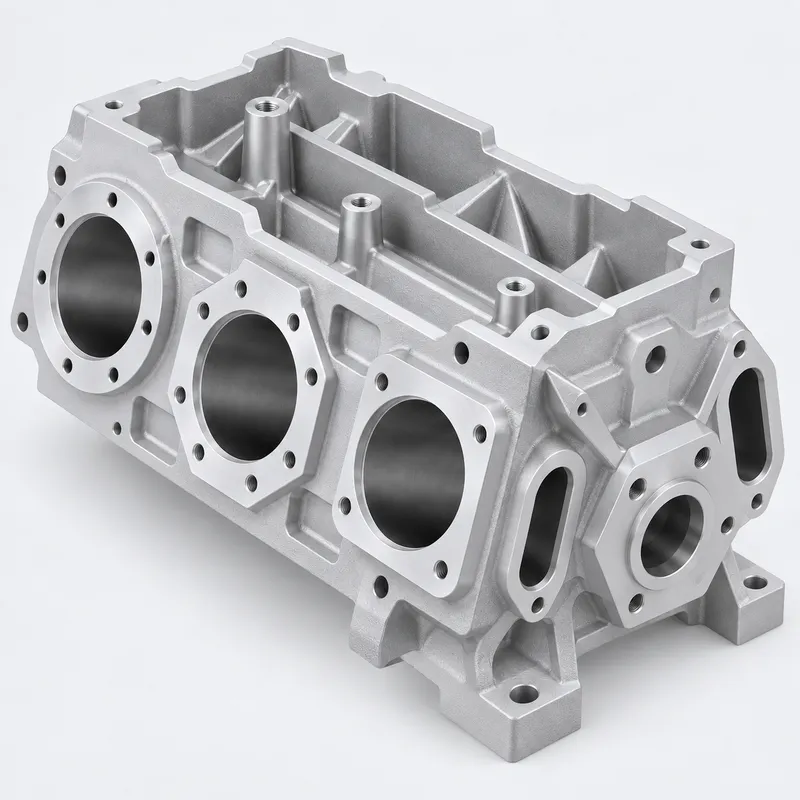
Three large circular openings are positioned along one side. Each opening has a different surrounding mounting profile and bolt-hole pattern, suggesting that the frame supports multiple internal or external components. Their diameter, spacing and alignment are important to the final assembly.
The recessed areas between the openings reduce weight while retaining material around the load-bearing sections. At the top, the frame has an open construction divided into separate internal channels. Triangular ribs reinforce the walls, while raised bosses provide threaded attachment points without requiring a uniformly thick structure.
The end face contains another group of functional features, including a central bore, elongated ports and threaded mounting holes. Because these details are located on the side, top, interior and end of the part, the component requires extensive multi-face machining.
Why Five-Axis CNC Machining Was Suitable
Producing these features with conventional machining would require several separate setups. Each additional setup introduces another opportunity for locating variation, particularly when the large side bores must remain correctly positioned relative to the end face.
Five-axis CNC machining allows the part to be oriented toward the cutting tool while retaining the original coordinate system. This provides more direct access to the internal pockets, side holes, threaded bosses and end features.
For this project, the process offered several practical benefits:
· Better control of bore-to-bore alignment
· Consistent positioning between side and end features
· Improved access to deep or partially obstructed areas
· Fewer fixture changes during multi-face machining
· Greater repeatability across all 18 components
The purpose of using five-axis machining was not simply to reach more surfaces. It was to preserve the geometric relationship between the functional interfaces.
Planning the Machining Datum
A reliable datum strategy was established before programming began. The first operations created stable reference surfaces that could be used throughout the remaining machining stages.
The three large bores, surrounding mounting pads and end interface were then machined within a controlled coordinate system. This approach reduced the risk of tolerance accumulation that can occur when related features are completed in independent setups.
The customer’s 3D CAD model defined the overall geometry, while the 2D drawing was used to confirm tolerances, threads and inspection requirements. Any unclear dimensions or inaccessible features needed to be resolved before material was cut.
Controlling Distortion in 7075 Aluminum
Aluminum 7075 offers a strong strength-to-weight ratio and is commonly selected for demanding structural components. However, this frame contains a large open cavity and requires substantial material removal from the original billet.
Removing too much material from one area at once can release internal stress and cause the frame to move. The machining sequence was therefore divided into controlled roughing, semi-finishing and finishing stages.
During rough machining, sufficient material was retained around the walls, bores and mounting faces. Critical features were completed later in the process after the main structure had been formed. Clamping pressure was also controlled to avoid deforming the open sections during machining.
Reaching Deep Pockets and Internal Features
The internal ribs and tall threaded bosses create restricted tool paths. Using an unnecessarily long cutting tool could reduce rigidity, increase vibration and affect dimensional accuracy.
Five-axis positioning allowed the cutting tool to approach these areas from more suitable directions. Shorter and more stable tools could be used for several recessed features, helping improve machining consistency.
During DFM review, we also considered:
· Internal corner radii
· Pocket depth and tool clearance
· Wall thickness around the large bores
· Access to threaded and cross-drilled holes
· Potential interference between the tool holder and ribs
· Suitable areas for secure workholding
If a feature cannot be machined reliably, our engineers discuss practical design adjustments with the customer before production.
Inspection Focus for the 18-Piece Batch
Inspection was based on the component’s assembly function. Particular attention was given to features that locate or connect other mechanical parts.
Key inspection points included:
· Diameters of the three large bores
· Center-to-center distance between openings
· Position of threaded holes
· Flatness of mounting surfaces
· Relationship between the side bores and end interface
· Wall thickness around recessed areas
· Consistency across all 18 parts
Threads and intersecting holes were also checked after deburring to ensure that no remaining chips or sharp edges would interfere with assembly.
Supporting Prototype and Low-Volume CNC Projects
An order of 18 pieces sits between initial prototyping and regular production. The customer receives enough components for assembly trials and equipment testing without committing to dedicated tooling.
If testing identifies a required change to a bore, mounting position or internal clearance, the CNC program can be updated for the next build. This makes five-axis CNC machining suitable for complex industrial equipment parts that are still progressing through engineering validation.
YS RAPID provides five-axis CNC machining services for aluminum prototypes and low-volume components. Our support covers DFM review, machining process planning, multi-process coordination, inspection and international delivery.
For a project review, please provide your STEP file, 2D drawing, material specification, quantity and critical tolerance requirements.
 EN
EN
 jp
jp  ko
ko  fr
fr  de
de  es
es  it
it  pt
pt  tr
tr  ar
ar  iw
iw