Multiple Ports Machined From Different Directions
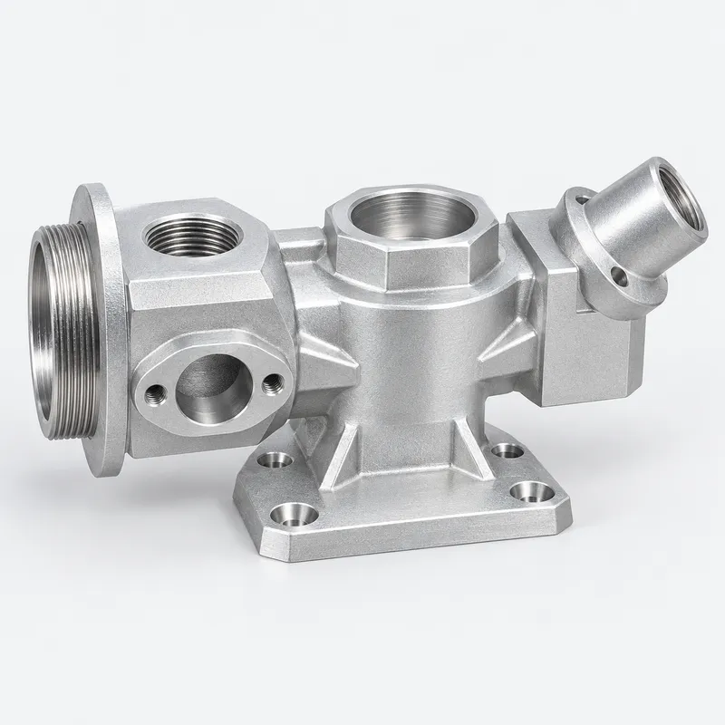
The housing incorporates a large threaded connection on one side, vertical threaded openings on the upper surfaces and an angled port on the opposite end. Four holes in the lower base locate and secure the component inside the equipment.
These features are connected by a single machined body, so their positions cannot be controlled independently. The direction of the angled port must correspond with the location of its mating component. The base holes must align with the equipment frame, and the threaded connections must remain accessible after installation.
For the customer’s engineering team, the 12 prototypes provide answers to practical assembly questions:
· Does the mounting base fit the equipment frame?
· Do the threaded components engage correctly?
· Is there sufficient clearance around the angled port?
· Can technicians reach the fasteners and connections?
· Is assembly performance consistent across all 12 parts?
The machining and inspection plan was organized around these functional relationships.
How Five-Axis CNC Machining Reduced Setup Changes
This housing requires machining from the top, bottom, sides and an angled direction. A conventional process would involve several separate setups, with the workpiece relocated for each group of features.
Every relocation introduces another datum transfer. When holes and threads on different faces must align with surrounding components, excessive setup changes can increase both machining time and positional variation.
Five-axis CNC machining provided direct access to more of the geometry from a controlled setup. It was used to machine the side connection, upper ports, angled feature, mounting holes and surfaces around the reinforcing ribs.
Fewer repositioning operations also supported the seven-day production cycle by reducing fixture changes and intermediate alignment checks.
Internal and External Thread Machining
The component contains both internal and external threads. These are functional interfaces that must accept the customer’s mating parts during assembly testing.
Before programming, the thread standards, effective depths and entry directions were checked against the 2D drawing. The 3D model was used to evaluate cutter access and possible interference from nearby walls.
Heavy rough machining was completed before the final thread operations. This protected finished threads from damage during subsequent material removal.
After machining, the thread entries were deburred to provide a clean lead-in. Inspection was then completed using the method defined for the project, such as suitable thread gauges or approved mating components.
Maintaining Stability Around the Mounting Base
The central body sits above the mounting base, leaving an open area underneath. Reinforcing ribs connect the two sections and support the housing around the threaded ports.
This structure is useful in the assembled equipment but creates a machining consideration. Removing the underside material too early could reduce support around the body and base.
The roughing sequence therefore retained material in selected areas while the main geometry was established. Functional faces, threaded ports and mounting holes were finished after the structure had become more stable.
Clamping pressure was also controlled to avoid temporarily distorting the mounting plate during machining.
Fine Bead Blasting and Clear Anodizing
After CNC machining and deburring, the aluminum housings were fine bead blasted. The process created an even matte texture across the flat surfaces, cylindrical ports, ribs and recessed transitions.
Blasting pressure and coverage required careful control around the thread entries, holes and defined edges. Excessive blasting could soften sharp details or produce an uneven texture around restricted areas.
The components were then clear anodized. This finish maintained the natural silver appearance of aluminum while improving surface corrosion resistance.
Because anodizing forms an oxide layer, close-fitting holes and threaded areas were considered during process planning. Masking or machining allowance can be applied when required by the customer’s drawing.
Completing the CNC Prototypes in One Week
The one-week lead time covered material preparation, CNC programming, machining, deburring, bead blasting, anodizing and final inspection.
To keep the project moving, the machining and finishing schedules were arranged before production started. All 12 components followed the same machining sequence and inspection criteria, providing the customer with a representative batch for assembly testing.
If the trial identifies a clearance or alignment issue, the CAD model and CNC program can be updated before low-volume production.
Five-Axis CNC Prototype Machining in China
YS RAPID provides five-axis CNC prototype machining in China for industrial equipment, automation systems, electronic devices and other engineered products.
We manufacture custom aluminum housings, multi-sided mechanical parts and low-volume CNC components based on customer-supplied 3D models and technical drawings.
For a machining review, send us:
· A STEP or other complete 3D model
· A 2D drawing with critical dimensions
· Material and surface-finish requirements
· Prototype quantity and target delivery date
· Details of important threads, mating faces and assembly features
Our team can review machining access, workholding, thread requirements and finishing details before production.
 EN
EN
 jp
jp  ko
ko  fr
fr  de
de  es
es  it
it  pt
pt  tr
tr  ar
ar  iw
iw