Why the Irregular Structure Needed 5-Axis CNC Machining
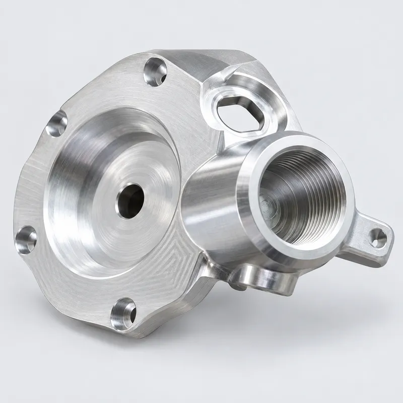
This component was not a simple plate, bracket or rectangular housing. Its structure included a large cylindrical port, recessed areas, mounting holes, angled surfaces and other features distributed around the body.
Producing these features on a conventional three-axis machine would require the part to be repositioned several times. Every additional setup could affect the relationship between bores, mounting faces and side features.
Five-axis CNC machining allowed the part to be approached from different orientations with fewer manual setups. This made it easier to machine the multi-sided geometry while controlling the positional relationship between functional features.
For an early-stage mechanical prototype, reducing setups also helped maintain consistency across all five parts. The customer could therefore compare assembly results without significant variation between prototypes.
Planning the Machining Sequence
The irregular shape created several practical machining challenges. Removing too much material at the beginning could reduce rigidity, while an unsuitable clamping position could block access to important features.
Before production, we reviewed the customer’s 3D model and 2D drawing to establish the machining sequence. The review covered:
· suitable datum and clamping surfaces;
· access to features on different sides;
· potential tool interference around the cylindrical section;
· material support during rough machining;
· the relationship between precision bores and mounting faces;
· inspection methods for the specified tolerances.
The aluminum stock was rough-machined first, with additional material retained around less rigid areas. Critical faces and bores were finished later in the machining process.
This sequence helped control deformation while allowing the necessary multi-face features to be completed efficiently.
Tolerances Based on Assembly Function
Not every dimension on a mechanical prototype requires the same tolerance. Specifying unnecessarily tight tolerances throughout the part can increase machining time and cost without improving the value of the test.
For this project, selected general dimensions were controlled to ±0.1 mm. The specified precision bores required a unilateral tolerance of 0/+0.05 mm because they interacted with mating parts during machine assembly.
The machining and inspection plan therefore focused on features affecting:
· mounting alignment;
· bore and insert fit;
· component location;
· clearance with surrounding parts;
· repeatable installation;
· movement or connection with mating components.
This function-based approach allowed the customer’s tolerance requirements to be applied where they mattered most.
Why Aluminum 6061-T6 Was Used
Aluminum 6061-T6 is widely used for functional mechanical prototypes because it provides a practical balance of strength, machinability, dimensional stability and low weight.
Compared with a visual model, a CNC-machined aluminum prototype can be installed using the intended fasteners and tested with real mating components. Engineers can use it to evaluate whether the structure is strong enough, whether the interfaces align correctly and whether any areas require design modification.
It is also suitable for producing low-volume metal prototypes when the development team needs several consistent parts rather than a single appearance model.
Inspection Before Delivery
Inspection was concentrated on the dimensions connected with assembly and function. The specified precision bores were checked separately from the general dimensions, and their relationship to the relevant mounting surfaces was verified.
Each component was also inspected for:
· burrs around intersecting holes;
· damaged or incomplete threads;
· sharp edges that could affect handling;
· machining debris inside recessed areas;
· visible damage on functional surfaces.
The five parts were cleaned, protected individually and packed for shipment to the United States. The complete project was finished within the required seven-day lead time.
CNC Prototypes for Early Mechanical Development
YS Rapid supports engineers who need custom metal prototypes for assembly trials, design verification and mechanical testing. Our capabilities include multi-sided aluminum components, equipment housings, structural parts, complex brackets and other low-volume machined prototypes.
For a new 5-axis CNC prototype machining project, customers can provide:
· a 3D CAD model;
· a dimensioned 2D drawing;
· material requirements;
· required quantity;
· critical tolerances;
· surface finishing requirements;
· the expected delivery date.
Reviewing this information together helps us identify critical features, select a practical machining route and prepare the parts for their intended engineering test.
Frequently Asked Questions
Can five aluminum prototypes be produced without tooling?
Yes. CNC machining produces the parts directly from aluminum stock, so dedicated molds are not required. It is suitable for early development quantities such as one, five or ten prototypes.
What information is required for a five-axis CNC prototype quotation?
A 3D model is normally used for machining and a 2D drawing should identify tolerances, threads, surface finishes and other controlled requirements. Quantity and delivery expectations should also be included.
Is a seven-day lead time possible for complex aluminum prototypes?
It may be possible depending on part size, geometry, material availability, tolerances and finishing requirements. The drawings must be reviewed before the delivery schedule is confirmed.
 EN
EN
 jp
jp  ko
ko  fr
fr  de
de  es
es  it
it  pt
pt  tr
tr  ar
ar  iw
iw