What the Buyer Needs from This Project
For a 1,000-piece order, the decision involves more than unit price. The supplier needs a stable process, a clear inspection plan and the capacity to deliver one consistent batch.
YS Rapid manages material sourcing, turn-mill production, thread verification, inspection and export packing through one team. First-article approval establishes the production reference; in-process checks control tool-wear changes. The same records can support repeat orders when the design remains unchanged.
The Machining Route Follows the Shaft’s Functional Sequence
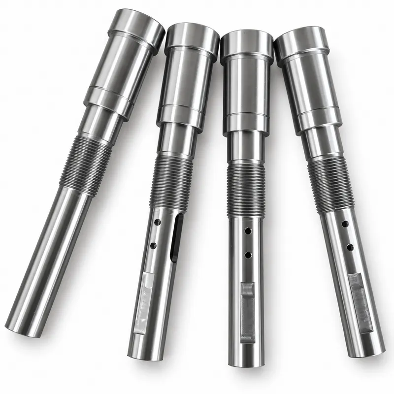
Outside diameters, faces, shoulders, reliefs and the external thread are machined according to the drawing’s datum structure. These features determine how the shaft is located, supported and tightened.
Driven tools then produce the transverse holes and elongated flat features. Completing these operations on a turn-mill machine reduces the need to transfer the partly finished shaft to a separate milling setup. This is particularly useful when the angular relationship between a hole and a flat affects installation.
Some rear-face details may still require a second operation. Where necessary, the setup is planned from an established diameter or face. The purpose of turn-mill shaft machining is to minimize avoidable datum changes and preserve the relationships that matter.
External Threads Must Work, Not Merely Look Correct
The long external thread is visually prominent, but appearance alone cannot confirm its function. Major diameter, pitch diameter, thread length, runout and entry condition all influence engagement with the mating component.
During production, thread dimensions are controlled according to the drawing and thread specification. The thread start and relief are checked for burrs that could cause resistance during assembly. An approved mating component can also support a practical fit check.
Because 316 stainless steel can generate heat and accelerate tool wear, thread-tool condition is monitored throughout the 1,000-piece run. A damaged insert or uncontrolled chip can affect both the thread surface and consistency across the batch.
Side Holes and Flats Need Positional Control
Cross holes and milled flats make this a functionally oriented shaft. The holes may accept locking pins or fasteners, while the flats may provide torque transmission, clearance or an assembly reference.
The production plan must consider:
The axial position of each side hole from the specified shoulder or end face
The angular relationship between holes and milled flats
Flat depth relative to the shaft centerline
Breakthrough burrs around cross-drilled features
Edge condition where the milled area meets the cylindrical surface
These details can affect assembly even when the main diameters are acceptable. First-piece inspection therefore verifies the complete feature relationship before batch production continues.
Maintaining Stability Across 1,000 Stainless Steel Parts
Batch CNC shaft machining requires control of gradual variation. Heat, insert wear, drill condition and chip accumulation may shift results during a long production run. Reliable chip control also helps protect shoulders and threads.
After first-article approval, selected functional dimensions are checked at planned intervals. Measurement trends guide tool-offset corrections, while drills and milling tools are replaced according to their actual condition.
Side holes and milled flats are deburred so their edges do not interfere with pins or mating parts. Finished shafts are cleaned, visually checked and separated during packing to protect threads and cylindrical surfaces.
Why 316 Stainless Steel Fits Automation Applications
316 stainless steel offers useful corrosion resistance and strength for locating, connecting and motion-related components. Because it is sensitive to heat buildup and work hardening, stable clamping, suitable cutting parameters and sharp tools help maintain repeatability. Material certification or passivation can be coordinated when specified.
Custom Shaft Production Managed as One Project
YS Rapid supports custom shafts combining CNC turning, external threading, cross drilling and milling. Work begins with the customer’s 2D drawing and 3D model, followed by a review of functional datums, mating features, tolerances and inspection requirements.
Our quality management supports controlled documentation and inspection. Buyers have one contact for machining, deburring, cleaning, dimensional checks, thread verification, fit checks and export packing.
Request a Quote for Batch Turn-Milled Shafts
For an accurate review, send YS Rapid the STEP file, dimensioned 2D drawing, material specification, thread standard, quantity and any mating-part information. Clearly identify the dimensions or feature relationships that affect installation and motion.
We will evaluate the shaft geometry, select a practical turning and milling sequence, and provide a quotation for your custom 316 stainless steel shaft production.
 EN
EN
 jp
jp  ko
ko  fr
fr  de
de  es
es  it
it  pt
pt  tr
tr  ar
ar  iw
iw