One Part, Four Assembly Interfaces
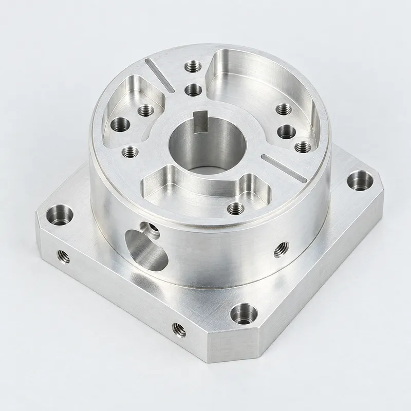
The visible geometry only tells part of the story. Each feature must be understood by what it connects to in the finished equipment.
Interface | Function in the assembly | Manufacturing attention |
Base mounting features | Position the component within the equipment frame | Hole location and mounting-face relationship |
Central opening and upper recesses | Provide location and clearance for the internal mechanism | Alignment, accessible edges and required clearances |
M3 tapped holes | Secure brackets, covers or adjoining parts | Thread position, usable depth and clean entry |
Side and corner holes | Accept hardware installed from other directions | Cross-face alignment and tool access |
Organizing the drawing this way helps distinguish locating features from ordinary clearance holes. It also directs inspection toward the dimensions that influence installation. A surface that sets component height, for example, must remain correctly related to the mounting base even if both dimensions pass separate checks.
Coordinated Production for Mating Components
Parts made by separate suppliers can each meet their own drawings and still require sorting, rework or manual adjustment during assembly. Typical causes include accumulated tolerances, inconsistent drawing revisions, finish buildup at close fits or hole patterns that do not align as a set.
For this project, the available 3D models, 2D drawings and assembly information were reviewed together. Related components could then be scheduled under one project plan, with attention to mounting faces, locating positions, fastener access, insertion direction and post-finish clearances.
Where mating components were available, fit verification provided a practical check in addition to individual measurements. It confirmed the intended assembly order and whether screws entered smoothly without forcing or cross-threading. If a mismatch appeared, the team could trace it to the relevant interface before packing.
For a purchasing team, this coordinated approach reduces supplier handoffs and makes responsibility clearer. Machining, related-part sourcing, finishing, inspection and assembly support are managed against the same drawing set and project requirements.
M3 Tapping That Works After Finishing
A tapped hole is only useful when the specified fastener can be installed correctly. The M3 features therefore need the required position, engagement and depth, together with a clean thread entry and controlled burr removal around the contact surface.
Surface treatment can also change the final condition of a small thread or close-fitting feature. When anodizing, conversion coating or another finish is specified, masking and coating allowance can be reviewed before processing. Thread and fit checks can then be completed in the finished condition required for assembly.
From Prototype Learning to Repeat Production
YS RAPID can support the same product as its purchasing needs change:
CNC prototypes for structural and installation checks;
low-volume parts for engineering builds and pilot assembly;
repeat CNC production after drawing approval;
coordinated metal, plastic, silicone and sheet metal components;
specified surface finishing, printing and part marking;
mating-part checks, subassembly and final inspection.
Keeping these stages within one managed route preserves technical context. Drawing revisions, approved requirements, interface notes and inspection priorities do not need to be rebuilt each time the project moves from prototypes to production or from machining to finishing.
A Clearer RFQ for Custom CNC Machining
An accurate quotation should define more than material and quantity. For custom metal CNC machining with assembly support, the most useful RFQ package includes:
3D CAD files and matching 2D drawings;
material grade and required surface treatment;
quantity and expected delivery schedule;
critical dimensions and inspection requirements;
BOM, mating-part files or an assembly model;
approved revision level and any special packing needs.
With this information, YS RAPID can quote the actual scope—from a single CNC aluminum component to coordinated machining, finishing, inspection and assembly. The result is a supply plan built around parts that need to work together, with fewer gaps between suppliers and fewer fit problems left for the customer to resolve.
 EN
EN
 jp
jp  ko
ko  fr
fr  de
de  es
es  it
it  pt
pt  tr
tr  ar
ar  iw
iw