Why This Part Required Five-Axis CNC Machining
On a conventional three-axis machine, the cutting tool mainly approaches the workpiece from one direction. Machining features on several sides normally requires the operator to remove, reposition and realign the part.
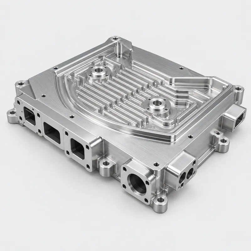
That approach may be suitable for simple components. For this aluminum prototype, however, repeated repositioning would make it more difficult to maintain consistent references between the detailed top geometry and the openings around the perimeter.
The component contained several machining challenges:
· Channels and raised features on the main surface
· Ports positioned on multiple side faces
· Holes with different machining directions
· Mounting tabs extending beyond the main body
· Features that had to remain aligned across different faces
· Restricted areas requiring careful tool and holder clearance
YS Rapid planned the component for 3+2 five-axis machining. The machine positioned the workpiece at controlled angles so that more features could be reached within a coordinated setup.
For a five-piece prototype order, this provided practical access to the multi-sided geometry without requiring complex production fixtures.
DFM Review and Machining Preparation
Before programming, our engineers reviewed the customer’s 3D CAD model and 2D drawing to understand the geometry, datum structure and critical interfaces.
The review considered:
· Which surfaces should be used as machining references
· How the aluminum blank could be held securely
· Whether the tools could reach recessed and side-facing features
· The clearance required for cutting tools and holders
· The order in which material should be removed
· Which dimensions required closer inspection
The 3D model defined the complete shape of the component, while the 2D drawing identified tolerances, datums, threads and other technical requirements. Reviewing both files helped us plan the machining process around the functional features rather than treating every surface in the same way.
Machining the Multi-Sided Aluminum Prototype
Production began with an aluminum blank large enough to provide stable workholding.
Rough machining removed the main volume of material and established the overall form. The toolpath sequence retained sufficient material to support the component while the major surfaces and channels were being produced.
After rough machining, semi-finishing and finishing operations created the top geometry, perimeter profile, mounting areas and smaller details. The five-axis setup then indexed the workpiece into the required orientations for machining the side ports, holes and other multi-directional features.
Using controlled rotations reduced the need to transfer the component between separate fixtures. It also helped keep features on the different faces related to the same machining references.
The parts were deburred and cleaned after CNC machining, with attention given to the edges of holes, ports and mounting features.
Inspection of Features Across Multiple Faces
Inspection of a multi-sided mechanical part involves more than checking its overall length, width and height.
A side port may need to align with another component in the customer’s assembly. A mounting hole may be positioned from a datum on the top surface. Features machined from different directions may also need to maintain a specified distance or orientation.
Inspection therefore followed the customer’s drawing and focused on the applicable functional requirements, including:
· Overall part dimensions
· Hole and port sizes
· Feature locations
· Mounting interfaces
· Relationships between different machined faces
· Threads and drawing-defined details
The same approved CNC program and machining sequence were used for all five prototypes to provide a consistent set of parts for the customer’s evaluation.
Why CNC Machining Was Suitable for Five Prototypes
For a quantity of five, CNC machining allowed the customer to obtain aluminum components directly from CAD data without investing in molds or other production tooling.
The machined prototypes included the actual mounting surfaces, holes, ports and mechanical interfaces required by the design. They could therefore be used to evaluate fit, installation and component layout before the customer moved to the next development stage.
Five-axis CNC prototyping is particularly suitable for low-quantity parts such as:
· Custom machine components
· Robotics and automation parts
· Equipment housings
· Structural frames and mounting plates
· Test fixtures
· Parts with features on several faces
What to Provide for a Five-Axis Prototype Quote
To review your project, please provide:
· A 3D CAD file, such as STEP
· A 2D drawing with tolerances and datums
· The required aluminum grade
· Prototype quantity
· Thread and insert specifications
· Surface finish requirements, if applicable
· Critical mating or assembly information
· Delivery destination
Supplying both the 3D model and 2D drawing allows us to review the complete geometry while identifying the dimensions that are most important to the application.
Five-Axis Aluminum Prototype Machining at YS Rapid
YS Rapid supports fast and flexible production of custom metal prototypes for mechanical engineering and product development projects.
For components with features on several faces, our team reviews the machining directions, workholding method, tool access and drawing requirements before production. We then plan a practical CNC machining route based on the part geometry and required quantity.
If you need one complex development part or a small batch of aluminum prototypes, send us your CAD files and project requirements. We will review the design and provide a quotation for your five-axis CNC prototype machining project.
 EN
EN
 jp
jp  ko
ko  fr
fr  de
de  es
es  it
it  pt
pt  tr
tr  ar
ar  iw
iw