A CNC Prototype Designed for Assembly Testing
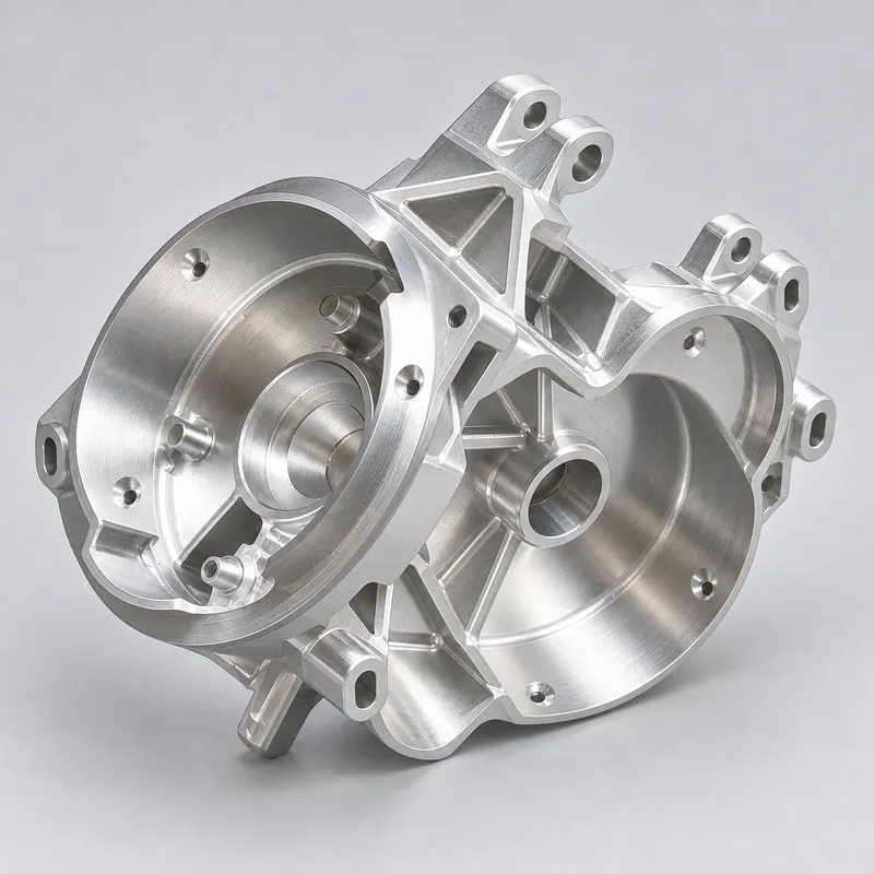
The two circular sections form the main functional areas of the frame. Each section includes a recessed cavity, a central bore and surrounding mounting holes. The upper and side lugs provide additional connection points, while the ribs help support the open structure.
Although these features can be inspected individually, their relationship determines whether the customer’s mating components will assemble correctly. If the center distance between the two bores changes, or a mounting lug is offset from its intended datum, the internal assembly may bind or fail to align.
The 10 aluminum prototypes were therefore machined as functional engineering parts rather than appearance models. They allow the customer to check:
· Alignment between the two circular sections
· Fit of components installed in the recessed areas
· Fastener access around the mounting lugs
· Clearance for neighboring electronic and mechanical parts
· Frame stability after the fasteners are tightened
· Repeatability across more than one prototype
This small batch provides more practical assembly information than a single sample.
Why Five-Axis CNC Machining Was Used
The component has holes, recesses and mounting faces pointing in different directions. Producing every feature with conventional three-axis machining would require several independent setups.
Frequent repositioning can make it more difficult to maintain the relationship between features machined from opposite sides. It can also increase handling time and create additional variation between parts.
Five-axis CNC machining provided better access to the deep circular areas, angled lugs, side holes and connecting surfaces. More related features could be machined from a consistent datum with fewer workholding changes.
This approach was particularly useful for controlling:
· The relative position of the two central bores
· Mounting holes located on different faces
· Machined surfaces inside the circular recesses
· Angled features with restricted tool access
· Edge transitions around the internal ribs
Tool reach and holder clearance were reviewed before machining so that cutters could enter the deeper sections without contacting nearby walls.
Machining Aluminum 7075 With an Open Structure
Aluminum 7075 offers high strength at a relatively low weight, making it suitable for internal structural components. However, the final condition of this part depends on more than material strength.
A considerable amount of stock must be removed to form the two recessed areas. The remaining frame includes open sections, ribs and projecting mounting lugs. Removing too much material from one side at once could reduce stability or allow stress in the stock to affect the finished geometry.
The machining sequence was arranged to keep sufficient support around sensitive areas during roughing. Final material was removed progressively before the critical bores, mating faces and mounting features were finished.
Clamping forces also had to be controlled. Excessive pressure on the open frame could temporarily distort the part during machining and allow it to move after release.
Clear Anodizing Without Sandblasting
The customer specified clear anodizing and requested no sandblasting.
This finish preserves more of the natural machined appearance of the aluminum. Fine cutter patterns may remain visible, which is acceptable for an internal component, but scratches, dents and rough edge transitions cannot be hidden by a blasted texture.
The parts were therefore deburred and handled carefully before anodizing. Attention was given to cavity edges, mounting lugs and other areas that could be marked during transportation between operations.
Anodizing requirements should also be considered when reviewing threads, fitted bores and mating surfaces. The oxide layer adds a small amount of thickness, so close-fitting features may require dimensional allowance or masking according to the customer’s drawing.
From Metal Prototype Machining to the Next Revision
Using the intended 7075 aluminum material gives the engineering team a more representative result than testing a visual model made from a substitute material.
After assembling the 10 samples, the customer can identify whether any bore position, mounting feature, clearance or tool-access area needs to be adjusted. Design revisions can then be applied to the CAD model before low-volume CNC production begins.
This is where CNC prototype machining is particularly useful: complex metal components can be tested without waiting for dedicated tooling, while subsequent revisions can be introduced through updated machining programs.
Five-Axis CNC Prototype Machining at YS RAPID
YS RAPID provides custom metal prototype machining and low-volume CNC manufacturing for electronic equipment, automation systems, robotics, medical devices and industrial products.
Our machining support includes:
· Aluminum CNC prototype machining
· Five-axis CNC milling
· Multi-sided metal components
· Precision bores and threaded holes
· CNC turning and turn-mill machining
· Anodizing and other surface finishes
· Prototype inspection and small-batch production
For quotation, send us your 3D model, 2D drawing, material grade, quantity and surface-finish requirements. If certain bores, mounting faces or hole positions affect assembly, identify them on the drawing so they can be considered during process planning and inspection.
YS RAPID can support your project from the first five-axis CNC prototype to assembly samples and low-volume production.
 EN
EN
 jp
jp  ko
ko  fr
fr  de
de  es
es  it
it  pt
pt  tr
tr  ar
ar  iw
iw