Machining Features That Must Work Together
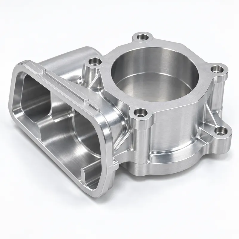
The large central bore is the main functional feature, but it cannot be machined independently from the surrounding structure. The mounting holes locate the housing during installation, while the open side section connects with another part of the equipment.
If the bore, mounting face and hole pattern are produced from unrelated references, small setup errors can accumulate. Each individual dimension may appear acceptable, but the complete housing can still create alignment problems during assembly.
Five-axis CNC machining provided access to the different faces while reducing repeated repositioning. More importantly, it allowed the central bore, mounting bosses, side opening and related surfaces to be machined around a consistent reference system.
This approach was more reliable than creating a separate setup for every machining direction.
Building the Process Around the Customer’s Drawings
The customer provided both a 3D CAD model and a controlled 2D manufacturing drawing.
The 3D model helped us understand the complete geometry, including tool access around the deep bore, reinforcing sections and open side frame. The 2D drawing defined the dimensional requirements, hole details, surface finish and inspection criteria.
Before programming, we reviewed three important points:
1. Which surfaces should be used as the primary machining references?
2. At what stage should the main bore and mounting holes be finished?
3. Which assembly-related dimensions could be influenced by material removal or anodizing?
These decisions established one controlled process for all 50 parts. This is essential in small-batch CNC production, where an acceptable first part is not enough—the same result must be maintained throughout the batch.
Controlling 7075 Aluminum During Machining
7075 aluminum provides high strength with relatively low weight, making it suitable for structural components used in industrial equipment. However, parts with large cavities, open sections and uneven wall thicknesses require a carefully planned machining sequence.
A substantial amount of material had to be removed to form the cylindrical chamber and side opening. Finishing the critical dimensions immediately after heavy roughing could allow released material stress to affect the final geometry.
For this reason, roughing and finishing were separated. Most of the material was removed first, while sufficient stock remained on the important functional surfaces. The bore, mounting faces and related holes were finished after the part had reached a more stable condition.
Clamping pressure was also controlled around the open side structure. Excessive force in this area could temporarily distort the walls during machining and allow them to move after the part was released.
Producing 50 Parts as One Consistent Batch
A 50-piece order cannot be treated as 50 unrelated prototypes. The fixture position, clamping force, cutting tools and inspection timing must remain consistent from the first part to the last.
A repeatable locating method was used so that every blank referenced the same functional areas. The first completed housing was inspected against the customer’s drawing before the remaining parts proceeded through production.
During machining, we monitored the features most closely related to assembly:
· Diameter and position of the central bore
· Mounting-hole locations relative to the bore
· Flatness of the assembly surfaces
· Wall condition around the open side frame
· Edges around intersecting holes and internal features
· Dimensional consistency across the production batch
Inspection was carried out at planned intervals rather than waiting until all 50 parts were complete. This allowed tool wear or dimensional movement to be identified before it could affect the remaining quantity.
Clear Anodizing for Finished Industrial Components
After machining and deburring, the housings received clear anodizing. This treatment improves corrosion resistance while retaining the natural metallic appearance of the 7075 aluminum.
Because clear anodizing does not hide scratches or inconsistent surface preparation, the parts were checked carefully before finishing. Machined edges were deburred, internal areas were cleaned, and visible surfaces were protected from unnecessary handling damage.
Anodizing can also influence the effective size of fitted or threaded features. Functional areas were therefore managed according to the drawing rather than treating surface finishing as a purely cosmetic operation.
Following anodizing, the housings were inspected again for appearance, damaged edges, blocked holes and assembly-related dimensions. The customer received finished components ready for installation, not unfinished machined blanks.
Completing the Batch Within Three Weeks
The three-week lead time covered drawing review, CNC programming, fixture preparation, 7075 aluminum machining, in-process inspection, clear anodizing and final quality control.
Surface finishing was included in the production schedule from the beginning. Coordinating machining and anodizing in advance helped prevent the completed parts from waiting unnecessarily between processes.
This project demonstrates how low-volume 5-axis CNC machining can support industrial equipment manufacturers that need more than a few prototypes but do not require high-volume production. The process combines access to complex geometry with the fixture control, inspection planning and batch consistency required for repeatable small-volume manufacturing.
CNC Machining Support for Similar Industrial Parts
This manufacturing approach is suitable for equipment housings, structural frames, automation components and other aluminum parts with multiple machining directions or closely related assembly features.
For a practical manufacturing review, customers can provide:
· A 3D CAD model
· A controlled 2D drawing
· Material and heat-treatment requirements
· Required quantity
· Surface treatment specifications
· Critical assembly dimensions
· Target delivery date
These details allow us to evaluate tool access, fixture requirements, machining sequence, inspection methods and finishing allowances before confirming the quotation and production schedule.
 EN
EN
 jp
jp  ko
ko  fr
fr  de
de  es
es  it
it  pt
pt  tr
tr  ar
ar  iw
iw