Why the Parts Required 5-Axis CNC Machining
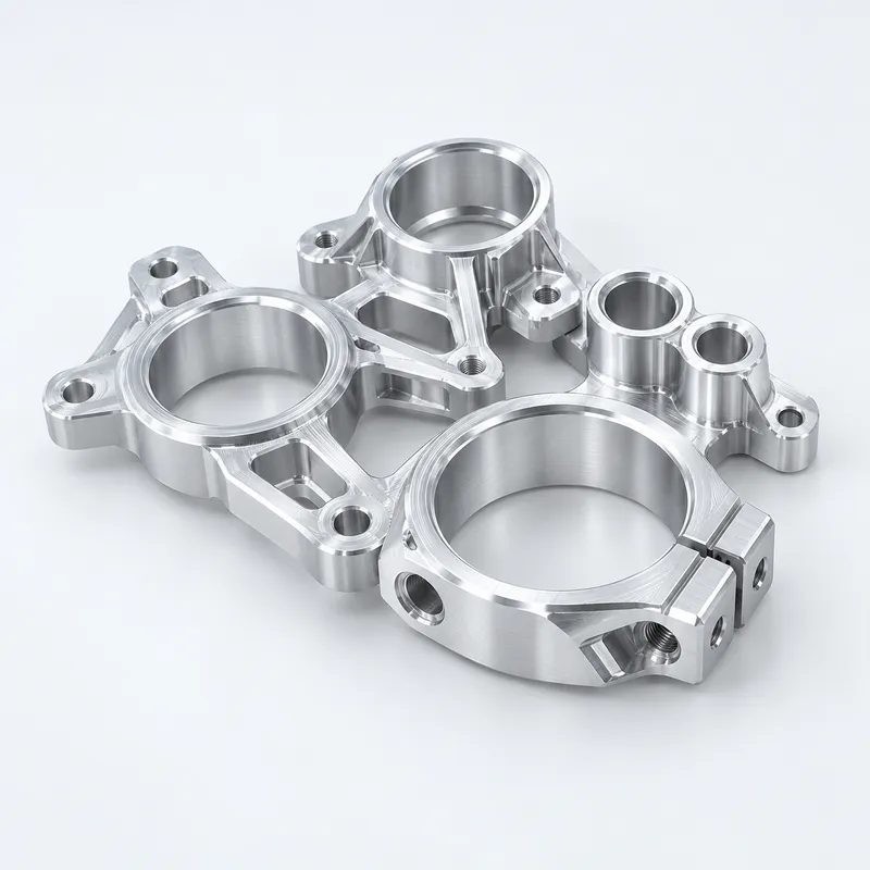
Although the components were relatively compact, their machining requirements were not limited to one or two directions. Important bores, side holes, mounting faces, pockets and connecting features were positioned at different angles.
Manufacturing these features through numerous independent setups could introduce variation between related surfaces. For example, a bore might meet its diameter tolerance but still create an assembly problem if its position were incorrect relative to the mounting holes on another face.
Using 5-axis CNC machining provided better access to the multi-sided geometry and allowed more related features to be completed within controlled setups. This helped us maintain alignment between functional areas while reducing unnecessary repositioning of the workpiece.
The machining method was selected according to the actual geometry and validation requirements of the prototype, rather than simply because the part appeared complex.
Machining Aluminum 6061-T6 Prototype Parts
Aluminum 6061-T6 was specified for its combination of machinability, strength, dimensional stability and low weight. Using the intended engineering material also gave the customer more meaningful results during structural and functional testing.
The parts were first rough machined to remove the main volume of material. Stock was retained around critical features for subsequent finishing. The machining sequence was planned carefully because uneven material removal can release internal stress and affect the relationship between features on different faces.
During production, particular attention was given to:
· Large machined bores and their corresponding mounting features
· Hole positions across different faces
· Contact and assembly surfaces
· Local wall thickness around pockets and openings
· Chamfers, edges and areas with restricted tool access
· Drawing dimensions specified with a tolerance of ±0.05 mm
The ±0.05 mm requirement applied to the identified functional dimensions. Other features were controlled according to the drawing and their importance within the assembly. This avoided adding unnecessary machining time and cost to non-critical areas.
Datum Control for Multi-Sided Features
For this type of structural prototype, inspecting each dimension separately is not enough. The relationship between features is often more important than an individual hole or surface.
Before CNC programming, the 3D model and 2D drawing were reviewed to identify the main datums, functional dimensions and assembly interfaces. Workholding and machining orientations were then planned around these references.
Critical dimensions were checked during machining and again before surface treatment. Completing dimensional inspection before bead blasting and conversion coating allowed machining issues to be identified at an earlier stage.
After finishing, the parts received a final visual and dimensional check to confirm that important holes, threads and mating areas remained suitable for assembly testing.
Fine Bead Blasting and Chromate Conversion Coating
Fine bead blasting was used to create a clean and consistent surface across the machined components. The blasting process reduced visible differences between machining areas while retaining the industrial appearance required for an engineering prototype.
Blasting parameters had to be controlled around sharp edges, mating surfaces and precision features. Excessive blasting could soften defined edges or alter the condition of closely fitted areas.
The parts were subsequently treated with chromate conversion coating to improve the corrosion resistance of the aluminum surface. Before processing, the finishing requirements were reviewed to identify any threads, bores or contact surfaces that required special attention or masking.
If a component has electrical grounding, bonding or specific cosmetic requirements, the coating type, appearance and masking areas should be clearly stated on the drawing or confirmed before production.
Prototypes Made for Engineering Validation
These eight parts were not produced only as presentation samples. Their main purpose was to help the customer assess the design before moving to the next manufacturing stage.
The finished aluminum prototypes could be used to verify:
· Overall dimensions and structural proportions
· Alignment between bores and mounting holes
· Fit with mating components
· Clearance around adjacent parts
· Access to screws and assembly tools
· Rigidity under preliminary functional testing
· Possible design changes before a larger production order
Producing a small batch also allowed the customer to assemble and compare several units rather than relying on the result from a single sample.
Aluminum Prototype Machining at YS RAPID
YS RAPID provides CNC prototype machining for custom aluminum parts used in product development, assembly trials and functional testing. We review the supplied CAD files and drawings to determine machining access, datum selection, critical tolerances, workholding and surface-treatment requirements.
For a new project, please provide:
· 3D CAD files and 2D drawings
· Required aluminum grade
· Prototype quantity
· Critical tolerances and datum information
· Surface finish and masking requirements
· Assembly or functional requirements
Understanding how the part will be tested helps us focus machining and inspection on the features that matter most to the prototype.
 EN
EN
 jp
jp  ko
ko  fr
fr  de
de  es
es  it
it  pt
pt  tr
tr  ar
ar  iw
iw