Why CNC Machining Was Used for the Prototype
The customer needed functional metal parts for assembly and engineering evaluation. CNC machining allowed the housings to be made in the specified 6061-T6 aluminum rather than a substitute prototype material.
This provided production-relevant mechanical properties, functional mounting features and a surface suitable for the intended finish. For an order of 10 sets, CNC machining was also more practical than investing in casting dies or other production tooling before the design had been fully verified.
Aluminum 6061-T6 is commonly selected for equipment housings because it combines good machinability, strength, corrosion resistance and suitability for anodizing.
Machining a Large Aluminum Housing
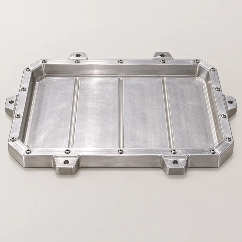
Producing a housing of this size requires more than machining its visible profile. Its broad surfaces, perimeter frame and projecting mounting ears must remain correctly aligned throughout multiple machining operations.
Removing material unevenly from a large aluminum workpiece can release residual stress and cause dimensional movement. This may affect the flatness of the main surface, the position of the outer frame or the alignment of the mounting features.
Before machining, our engineering team reviewed the customer’s 3D model and 2D drawing, paying particular attention to:
· Overall part dimensions and material thickness
· Flatness requirements on the main surfaces
· Perimeter-frame geometry
· Mounting-ear positions
· Hole and thread locations
· Datum selection between machining setups
· Surfaces related to assembly or sealing
· Areas that could be affected by distortion
Material was removed progressively, with allowance retained on important surfaces for later finishing. This gave the workpiece time to stabilize before the final dimensions, mounting features and surface relationships were completed.
Workholding and Machining Sequence
The mounting ears extended beyond the main body of the housing, which limited the available clamping positions. The workholding method had to support the part securely without obstructing the outer profile or deforming the broad machined surfaces.
The machining sequence was planned around consistent datums so that the inner surface, perimeter frame, mounting ears and holes remained correctly aligned. Excessive clamping force was avoided because it could temporarily distort the workpiece and affect its dimensions after removal from the fixture.
Important holes were finished after the main material-removal operations to reduce the possibility of their positions being affected by part movement. Threads were then checked for size, depth and condition before surface treatment.
Sandblasted and Anodized Surface Finish
After CNC machining and deburring, the housings were prepared for fine sandblasting. This process reduced visible differences between individual tool paths and created a more uniform matte texture.
Surface preparation was important because anodizing does not conceal scratches, dents or poor handling marks. In some cases, it can make these defects more noticeable. The parts were therefore visually inspected before being sent for anodizing.
After surface treatment, each housing was checked for:
· Consistent sandblasted texture
· Acceptable anodized appearance
· Scratches, dents or handling marks
· Finish quality around edges and mounting ears
· Blocked or damaged threaded holes
· Surface-treatment requirements specified on the drawing
The completed parts were handled and packed separately to reduce metal-to-metal contact during transportation to Germany.
Dimensional Inspection and Batch Consistency
Inspection of an aluminum housing prototype should focus on the features that influence assembly and functional testing. Measuring only the overall length and width would not confirm whether the part could be installed correctly.
Inspection for this project included:
· Overall length, width and thickness
· Main-surface flatness
· Perimeter-frame dimensions
· Mounting-hole positions and diameters
· Thread specifications and condition
· Mounting-ear locations
· Relationships between relevant assembly features
Critical dimensions were inspected according to the customer’s 2D drawing. The 10 housings were also compared for batch consistency because the customer needed interchangeable parts for the same equipment assembly rather than individually adjusted samples.
Custom Metal Prototype CNC Machining
YS RAPID provides custom metal prototyping for aluminum housings, equipment covers, brackets, frames, base plates and other machined components. Depending on the geometry and project requirements, our work can include CNC milling, CNC turning, surface finishing, dimensional inspection and low-volume production.
For large aluminum components, we review material condition, workholding, machining sequence, surface relationships, distortion risk and finishing requirements before production begins.
This engineering review helps customers receive prototypes that can be used for assembly, fit checking and design validation—not only visual presentation.
Request a Quote for an Aluminum Prototype
For a metal prototype CNC machining quotation, please provide:
· 3D CAD model
· 2D drawing with tolerances
· Material grade and condition
· Surface-finish specification
· Required quantity
· Critical assembly or functional features
· Delivery destination
YS RAPID will review the files and provide feedback on machinability, lead time and the proposed production process.
 EN
EN
 jp
jp  ko
ko  fr
fr  de
de  es
es  it
it  pt
pt  tr
tr  ar
ar  iw
iw