Why the Turning Datum Mattered
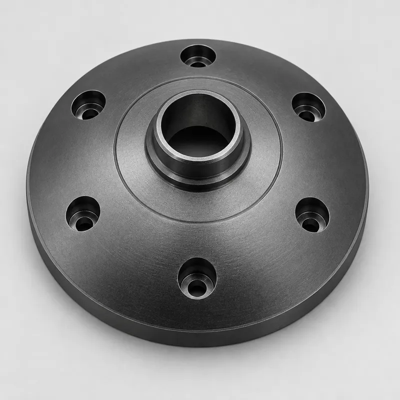
The center bore and raised collar provide natural reference features for this type of flange. The broad circular face can also influence how the part seats against the mating structure. These surfaces therefore need to be considered together rather than machined as unrelated dimensions.
During CNC turning, the outside diameter, mounting face, center bore, collar and concentric groove were machined around a common rotational axis. Establishing these features in a controlled turning sequence helped maintain concentricity and reduced the chance of accumulated setup error.
Adding the Mounting Pattern Without Losing Alignment
The six counterbored holes could not be completed by turning alone. They required a secondary CNC operation, but their position still had to remain consistent with the central bore and turned outside diameter.
For the secondary setup, the turned features were used as references for locating the component. This connected the bolt-circle position back to the original turning datum. The machining plan considered:
Equal angular spacing between the mounting holes
Bolt-circle position relative to the center bore
Counterbore diameter and depth
Remaining wall thickness near the outer edge
Burr control at the hole entrances and exits
This relationship is important in optical automation assemblies, where the flange may support a sensor, lens-related module, rotary mechanism or other aligned component. The hole pattern does not need to be visually symmetrical only; it must locate the part repeatably during assembly.
Small-Batch Production With Repeatable Setups
For a quantity of 15 parts, the goal was to achieve production-level consistency without treating the order like mass production. The first component was used to confirm the turning dimensions, face relationship and mounting-hole positions before the remaining parts continued.
Once the process was confirmed, the same machining sequence and inspection points were maintained across the batch. This helps avoid gradual variation in the bore, collar height or counterbore depth.
Planning for Black Anodizing
Black anodizing was specified for surface protection and a consistent appearance. For optical and electronic equipment, the dark finish can also reduce unwanted surface reflection compared with untreated aluminum.
Anodizing is not simply a cosmetic step added after machining. The coating changes the surface slightly, so fits and masking requirements need to be reviewed before production. Dimensions that interact with mating parts, threaded features and any surfaces requiring electrical contact should be identified on the drawing.
Before finishing, the parts were checked for machining defects that could remain visible after anodizing. After finishing, we reviewed color consistency, coverage and the condition of functional features.
Inspection Around the Assembly Function
Inspection focused on the features that control how the flange locates and mounts:
Center-bore diameter
Concentric relationship between the bore and outside diameter
Collar diameter and height
Mounting-face condition
Bolt-circle and hole-position accuracy
Counterbore dimensions
Overall profile and anodized finish
This function-based inspection is more useful than checking a long list of dimensions without considering how the part is installed. Where customers can provide the mating model or assembly drawing, we can also review potential clearance and datum issues before machining begins.
Low-Volume CNC Turning at YS Rapid
YS Rapid provides low-volume CNC turning for aluminum prototypes and small production batches used in optical systems, automation equipment, electronic instruments and test devices. Projects can combine turning with milling, drilling, tapping, anodizing and dimensional inspection when a part contains both rotational and off-axis features.
For a faster manufacturing review, send us:
3D CAD model and dimensioned 2D drawing
Material grade and temper
Critical datums, fits and geometric tolerances
Anodizing specification and masking requirements
Prototype quantity and expected follow-on volume
Mating-part or assembly information when available
If your design includes a circular housing, flange, end cover or locating component, our team can review the feature relationships and plan a practical route from CNC aluminum turning through finishing and final inspection.
 EN
EN
 jp
jp  ko
ko  fr
fr  de
de  es
es  it
it  pt
pt  tr
tr  ar
ar  iw
iw