The Main Risk Was Tolerance Interaction
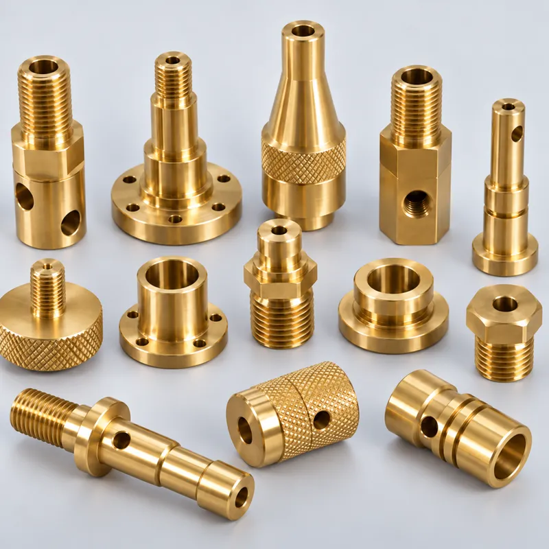
The challenge was not a single unusually complex component. It was the relationship between multiple precision brass components inside each instrument.
For example, a shaft and mating bore can both fall within their drawing limits but still produce a tighter or looser fit than expected when their tolerances combine. A shoulder position can affect the final installed height. A thread may pass a basic check but prevent a component from reaching its intended seating face. These are tolerance-interaction issues, and they become more important when the same assembly must be repeated across 50 sets.
Before machining, we reviewed the 3D models, 2D drawings and mating relationships together. The review identified which dimensions directly controlled insertion, seating, alignment and thread engagement. This allowed the inspection plan to focus on functional interfaces instead of treating every dimension as equally critical.
From Separate Part Numbers to Matched Sets
For this project, quantity control meant more than counting equal numbers of each component. The finished parts had to be organized into complete, usable sets for the customer’s prototype build.
First-off components were inspected before the remaining batch continued. During production, specified diameters, bores, shoulder distances and thread-related features were monitored for consistency. Parts were then kept organized by family so missing or mixed components would not delay the customer’s assembly work.
This matched-set approach also made it easier to evaluate how dimensional variation behaved at the assembly level. Instead of discovering fit problems after delivery, we could check the relevant interfaces while the components and inspection information were still available at our facility.
Controlling the ±0.01 mm Critical Features
The ±0.01 mm tolerance applied only to the dimensions identified as critical on the customer’s drawings. Applying the tightest tolerance to every feature would add machining and inspection time without improving the instrument’s function.
Measurement methods were selected according to the feature. Critical outside diameters and lengths were checked with suitable precision instruments. Bores, threads and mating features were verified with appropriate gauges or measuring equipment. We also paid attention to burrs at cross-holes, thread starts and small edges because a burr can obstruct assembly even when the nominal dimension is correct.
Inspection therefore addressed both numerical compliance and practical function:
Critical diameters and bores met the specified limits.
Shoulder positions supported the required installed height.
Threads engaged smoothly and reached the intended seating position.
Cross-holes and related features remained correctly located.
Components were clean and free from assembly-affecting burrs.
Trial Assembly as the Final Release Check
After dimensional inspection, related components were trial assembled. The purpose was not to build the complete electronic instrument, but to confirm the interfaces controlled by the brass parts.
We checked insertion, seating, thread engagement and relative positioning. If a fit had felt inconsistent, the dimensional records and mating components would have been available for immediate review. Completing this step before packing reduced the risk of the engineering team losing time on basic mechanical incompatibility during its prototype build.
The parts were released only after the specified dimensions and trial-assembly requirements had been confirmed.
Custom Brass CNC Parts for Instrument Development
YS Rapid provides brass prototype machining for electronic instruments, test equipment and other products that use multiple custom metal components. Support can include drawing review, production planning, precision machining, critical-dimension inspection, matched-set management and assembly-focused verification.
This service is particularly useful when:
Several brass components belong to the same prototype assembly.
Shafts, bores, shoulders or threads create functional interfaces.
Selected dimensions require tight tolerance control.
The engineering team needs complete sets for build and testing.
Prototype quantities may progress into low-volume production.
For an accurate quotation, send the 3D files and dimensioned 2D drawings for each part. An assembly drawing is also helpful because it shows how the components relate to one another. Please identify the critical fits, inspection requirements, brass grade, quantity per set and total number of sets.
If you need custom brass CNC parts that must work together in an electronic instrument, YS Rapid can review the component family and prepare a practical manufacturing and verification plan for your prototype build.
 EN
EN
 jp
jp  ko
ko  fr
fr  de
de  es
es  it
it  pt
pt  tr
tr  ar
ar  iw
iw