One Housing, Several Functional Directions
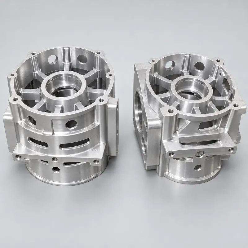
The central machined bore forms the main reference area of the housing. Around it are radial reinforcing ribs and a series of mounting features facing different directions. The outside of the part also contains circular holes, elongated openings and machined blocks for connection with surrounding components.
These features create three practical CNC machining concerns.
First, the central bore must remain correctly related to the external mounting surfaces. Second, the side holes must meet the housing at their specified positions and orientations. Third, the relatively open structure must remain stable while material is removed.
Treating each face as an independent machining operation would increase the number of setups. Every additional repositioning could introduce a small change in datum location. For a housing that carries bearings or rotating components, those changes may become visible during assembly even when individual dimensions appear acceptable.
Five-axis machining gave the cutting tools better access to the internal and external features while preserving a consistent reference system.
Machining Around Internal Ribs
The radial ribs are not decorative features. They reinforce the circular wall and connect the central bearing area to the outer body without adding excessive weight.
They also restrict tool access.
A suitable machining sequence was therefore needed to remove the bulk material without leaving the structure unsupported too early. Rough machining established the main internal space while retaining enough material around the bore and outer walls. The ribs, stepped surfaces and local recesses were then progressively finished with tools selected for reach and rigidity.
This sequence helped reduce vibration near the open sections and limited distortion around the central geometry. It also avoided unnecessary manual reorientation when machining areas located between the ribs.
Precision Holes: Diameter Alone Was Not Enough
Some holes were specified at ±0.05 mm. For this project, checking only the hole diameter would not have provided enough information.
A precision hole can meet its size requirement but still create an assembly problem if its position shifts relative to the central bore or mounting face. We therefore treated the precision holes as part of a connected feature system.
The inspection focus included:
· Hole diameter and position
· Relationship between the central bore and mounting faces
· Spacing between connection holes
· Thread condition and depth
· Flatness of assembly surfaces
· Dimensions that influence component fit
Critical bores and holes were completed after the surrounding geometry had reached a stable condition. This prevented heavy material removal later in the process from affecting already-finished features.
Why 6061-T6 Was Suitable for the Housing
Aluminum 6061-T6 provides adequate strength for many industrial structures while remaining easier to machine than harder aluminum grades. Its relatively low weight also makes it useful for equipment containing moving assemblies or modules that require regular maintenance.
For this housing, the material supported a combination of:
· Structural ribs
· Precisely machined bores
· Threaded mounting points
· Thin openings and relief areas
· Large internal material removal
Machining parameters still had to account for heat, tool reach and local wall thickness. A fast cutting strategy alone would not be appropriate because the geometry changes continuously around the part.
Managing Consistency Across 20 Parts
This was not a single display prototype. All 20 housings needed to fit the same mating components.
Before releasing the full quantity, the initial part was used to confirm the bore dimensions, tool accessibility, threaded features and key positional relationships. The verified machining program and datum strategy were then retained for the remaining parts.
In-process checks were placed after the operations most likely to influence final alignment. This made it possible to detect variation before the component reached the final stage rather than relying entirely on end-of-production inspection.
Five-Axis CNC Service for Industrial Development
This project shows where five-axis CNC prototype machining provides genuine engineering value. The benefit is not limited to producing visually complicated shapes. It is especially useful when several functional faces must remain aligned within one machined component.
YS Rapid supplies custom CNC machining for industrial housings, automation parts, motor components, robotics structures and mechanical development projects. Our work covers individual prototypes as well as low-volume orders that require stable dimensions from the first part to the last.
For parts with internal structures, precision bores or features facing several directions, provide both the 3D model and the tolerance-controlled drawing. We can evaluate tool access, datum selection and the machining sequence before production begins.
 EN
EN
 jp
jp  ko
ko  fr
fr  de
de  es
es  it
it  pt
pt  tr
tr  ar
ar  iw
iw