Can Large Medical Device Housings Be CNC Machined?
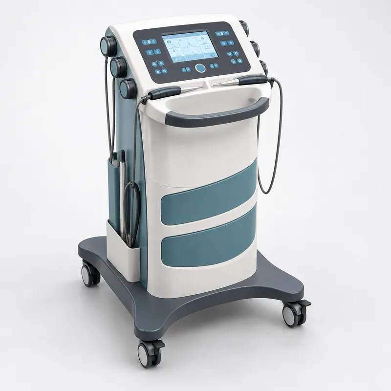
Yes. CNC machining is often suitable for medical device housings when engineers require a small number of prototypes before investing in injection molding tooling.
For this 10-set project, plastic CNC machining allowed the customer to evaluate:
· Overall equipment dimensions
· Housing shape and ergonomics
· Internal mounting features
· Control-panel installation
· Gaps between adjoining covers
· Accessibility of screws and connectors
· Compatibility with metal and purchased components
· Painted appearance of the assembled product
Compared with an appearance-only model, a CNC-machined plastic prototype can include mounting holes, threaded inserts, internal pockets and other engineering features required for assembly testing.
However, large plastic housings must be reviewed carefully. Deep cavities, enclosed ribs and narrow internal corners may be difficult or impossible to reach using standard CNC tools. Material movement and wall thickness also need to be considered when machining large plastic components.
Machining Features That Were Not Directly Accessible
Several internal areas of the housing could not be machined from a single plastic block without changing important exterior features. Instead of simplifying the design without approval, our engineers reviewed these areas with the customer.
We proposed dividing selected housings into separate machinable sections. Once the customer approved the approach, each section was CNC machined individually and then bonded to form the complete enclosure.
The split positions were selected based on:
· Assembly loads
· Visibility after installation
· Available bonding area
· Surface-finishing requirements
· Access for polishing
· Alignment with neighboring components
After bonding, the joints were blended and polished before painting. This made it possible to retain the required exterior geometry while avoiding unnecessary prototype tooling.
Using the Assembly Drawing to Plan Production
The customer supplied 3D models, 2D drawings and an assembly drawing. The assembly drawing was especially important because it showed how the upper control enclosure, front covers, handle, internal structure, side accessories and mobile base interacted.
Before machining, we reviewed:
· Housing-to-bracket mounting positions
· Hole alignment across different components
· Threaded inserts and fastening directions
· Clearance around the control panel
· Cable-routing space
· Access for tools during installation
· Alignment of adjacent exterior surfaces
· The required order of assembly
This review helped us establish which dimensions directly affected fit and which components should be completed first for the initial trial build.
Fit Problems Found During Trial Assembly
Once the first set of parts was ready, we assembled the complete prototype rather than inspecting every component only in isolation.
The trial assembly revealed local interference, inconsistent gaps between covers and several mounting areas that made installation difficult. These issues did not necessarily mean that one component was outside its drawing tolerance. In a multi-part prototype, small variations from several components can accumulate and affect the final assembly.
Our team documented the issues and communicated them to the customer with proposed adjustments. After receiving approval, we modified the relevant mating features and refined the assembly sequence.
The first unit was then assembled again to verify:
· Whether interference had been removed
· Whether the exterior gaps were more consistent
· Whether screws could be installed correctly
· Whether the covers aligned with the internal structure
· Whether the equipment could be assembled without forcing parts into position
Only after confirming the revised fit did we apply the changes to the remaining prototype sets.
Painting and Screen Printing
Following machining and assembly verification, the plastic housings were disassembled for surface finishing. CNC tool marks, bonded joints and local surface transitions were polished before painting.
The housings were painted according to the customer’s specified color requirements. Large front panels and curved surfaces received particular attention because they can make sanding marks, dust, coating buildup and gloss variation more visible.
Screen printing was completed after the coating had been inspected. Artwork position and orientation were checked against the drawings and the final assembly so that interface markings aligned with the control panel and surrounding features.
Final Assembly and Inspection
The painted components were assembled again with the metal parts, fasteners, control-panel elements and external accessories. Inspection covered both the individual parts and the complete equipment.
Checks included:
· Critical mounting dimensions
· Fit and alignment of plastic housings
· Gap consistency between covers
· Threaded insert and screw installation
· Control-panel opening and accessory clearances
· Handle and base stability
· Cable-routing space
· Paint color, gloss and surface condition
· Screen-printing position and appearance
· Overall condition of the assembled units
The approximately 10 completed sets were then protected for shipment to Canada.
One-Stop Medical Device Prototype Manufacturing
Medical equipment commonly combines parts made through several different processes. Coordinating them through one project team helps engineers evaluate the complete product rather than managing each component separately.
YS Rapid can provide:
· Plastic CNC prototype machining
· Aluminum and stainless-steel CNC machining
· CNC turning
· Sheet metal prototyping
· Silicone buttons and seals
· Urethane casting
· Threaded insert installation
· Bonding and polishing
· Custom painting
· Screen printing
· Trial assembly and fit adjustment
· Final inspection and international delivery
Our role is not limited to producing parts from CAD files. When an assembly issue appears during medical device prototyping, we communicate the problem, evaluate practical adjustments and verify the approved solution on the physical unit.
What to Send for a Medical Device Prototype Quote
To evaluate a multi-part medical equipment prototype, please provide:
· 3D CAD files
· 2D drawings with critical tolerances
· Assembly drawings
· Bill of materials
· Required quantity
· Plastic and metal material specifications
· Color reference or paint code
· Screen-printing artwork
· Purchased components used for fit checks
· Required testing or inspection points
If the design is still under development, we can review machining accessibility, part-splitting options, assembly clearances and surface-finishing requirements before production.
YS Rapid supports small-volume medical device CNC prototyping from individual plastic housings to fully finished and assembled equipment prototypes.
 EN
EN
 jp
jp  ko
ko  fr
fr  de
de  es
es  it
it  pt
pt  tr
tr  ar
ar  iw
iw